Z8 Microcontrollers
ZiLOG Counter/Timers
UM001601-0803 6-11
6.5.4 Retriggerable Input Mode
The T
IN
Retriggerable Input Mode (TMR bits 5 and 4 are set to
1) causes T1 to load and start counting on every occurrence of a
High-to-Low transition on T
IN
(Figure 6-17). Interrupt request
IRQ5 will be generated if the programmed time interval (deter
-
mined by T1 prescaler and counter/timer register initial values)
has elapsed since the last High-to-Low transition on T
IN
. In Sin-
gle-Pass Mode, the end-of-count resets the Enable Count bit.
Subsequent T
IN
transitions will not cause T1 to load and start
counting until software sets the Enable Count bit again. In Con
-
tinuous Mode, counting continues once T1 is triggered until soft-
ware resets the Enable Count bit. When enabled, each High-to-
Low T
IN
transition causes T1 to reload and restart counting. In-
terrupt request IRQ5 is generated on every end-of-count.
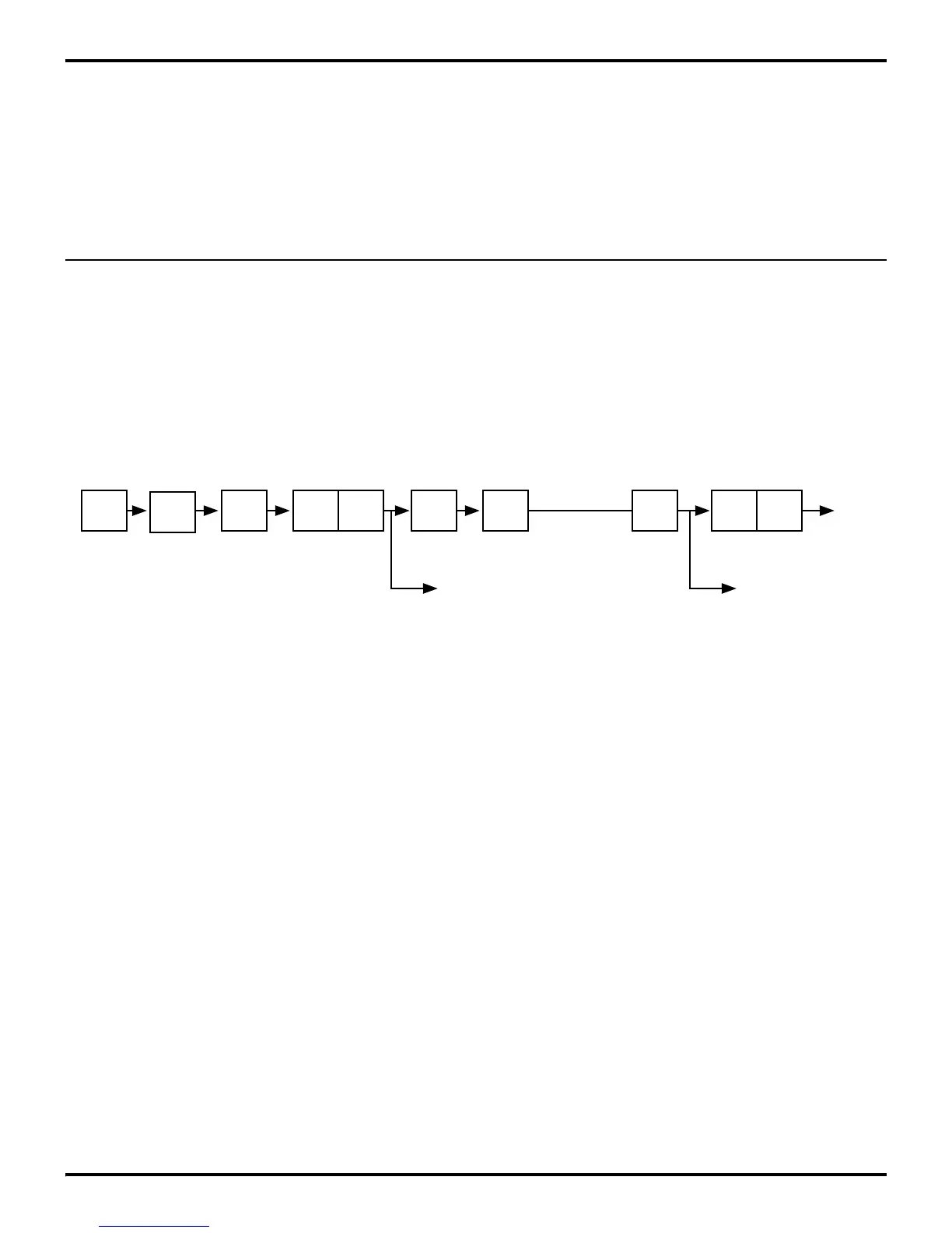
6.6 CASCADING COUNTER/TIMERS
For some applications, it may be necessary to measure a time in-
terval greater than a single counter/timer can measure. In this
case, T
IN
and T
OUT
can be used to cascade T0 and T1 as a single
unit (Figure 6-18). T0 should be configured to operate in Contin
-
uous mode and to drive T
OUT
. T
IN
should be configured as an ex-
ternal clock input to T1 and wired back to T
OUT
. On every other
T0 end-of-count, T
OUT
undergoes a High-to-Low transition that
causes T1 to count.
T1 can operate in either Single-Pass or Continuous mode. When
the T1 end-of-count is reached, interrupt request IRQ5 is gener
-
ated. Interrupt requests IRQ2 (T
IN
High-to-Low transitions) and
IRQ4 (T0 end-of-count) are also generated but are most likely of
no importance in this configuration and should be disabled.
Figure 6-18. Cascaded Counter / Timers
OSC
÷2 ÷4
PRE0 T0
÷2PRE1
IRQ
2
P3
1
P3
6
T1
IRQ
4
T
OUT
T
IN
IRQ
5
 Loading...

