Z8 Microcontrollers
I/O Ports ZiLOG
5-24 UM001601-0803
5.8 ANALOG COMPARATORS
Select Z8 devices include two independent on-chip analog com-
parators. See the device product specification for feature avail-
ability and use. Port 3, Pins P31 and P32 each have a comparator
front end. The comparator reference voltage, pin P33, is com
-
mon to both comparators. In Analog Mode, the P31 and P32 are
the positive inputs to the comparators and P33 is the reference
voltage supplied to both comparators. In Digital Mode, pin P33
can be used as a P33 register input or IRQ1 source. P34, P35, or
P37 may output the comparator outputs by software-program
-
ming the PCON Register bit D0 to 1.
5.8.1 Comparator Description
Two on-board comparators can process analog signals on P31
and P32 with reference to the voltage on P33. The analog func
-
tion is enabled by programming the Port 3 Mode Register (P3M
bit 1). For interrupt functions during analog mode, P31 and P32
can be programmable as rising, falling, or both edge triggered in
-
terrupts (IRQ register bits 6 and bit 7).
Note: P33 cannot generate an external interrupt while in this
mode. P33 can only generate interrupts in the Digital Mode.
Note: Port 3 inputs must be in digital mode if Port 3 is a Stop-
Mode Recovery source. The analog comparator is disabled in
STOP mode.
P31 can be used as T
IN
in Analog or Digital Modes, but it must
be referenced to P33, when in Analog Mode.
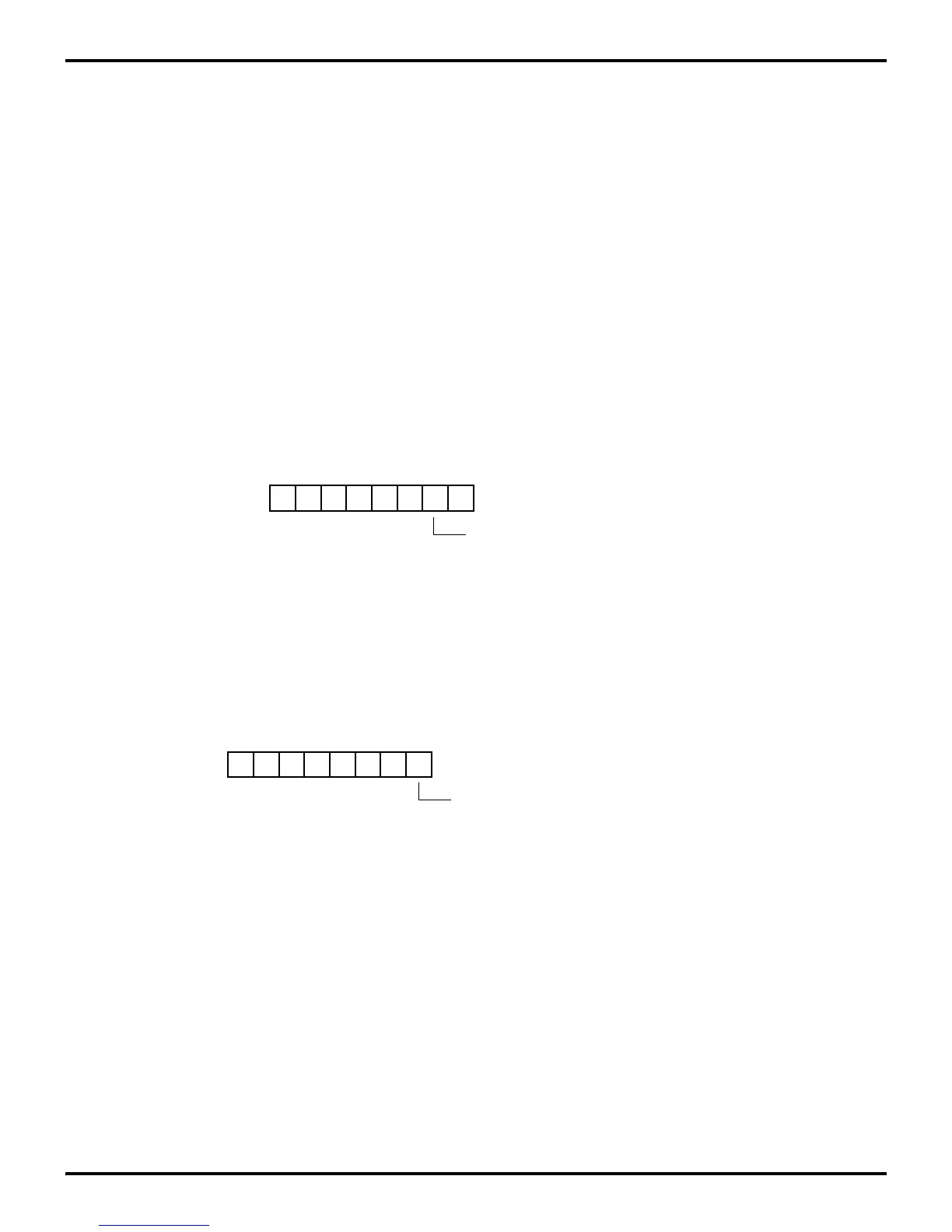
Figure 5-30. Port 3 Input Analog Selection
D1
(Write-Only)
0 = Digital Mode P31, P32, P33
1 = Analog Mode P31, P32, P33
Port 3 Mode Register (P3M)
Register F7H
Figure 5-31. Port 3 Comparator Output Selection
D0
(Write-Only)
0 = P34, P35, or P37 Standard Outputs
1 = P34, P35, or P37 Comparator Outputs
Port Configuration Register (PCON)
Register 00H
ERF Bank F