Z8 Microcontrollers
ZiLOG External Interface
UM001601-0803 10-5
10.6 BUS OPERATION
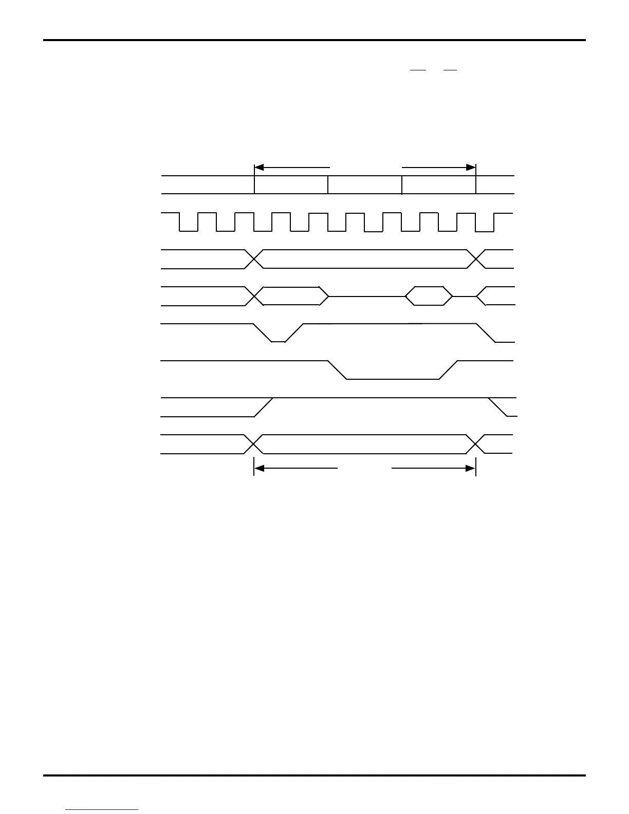
Typical data transfers between the Z8 MCU and External Mem-
ory are illustrated in Figures 10-5 and 10-6. Machine cycles can
vary from six to 12 clock periods depending on the operation be
-
ing performed. The notations used to describe the basic timing
periods of the Z8 are machine cycles (Mn), timing states (Tn),
and clock periods. All timing references are made with respect
to the output signals
AS and DS. The clock is shown for clarity
only and does not have a specific timing relationship with other
signals.
Figure 10-5. External Instruction Fetch or Memory Read Cycle
Machine Cycle
T1
T2*
T3
Clock
A15-A8
AD7-AD0
/AS
/DS
R/W
/DM
Read Cycle
A8-A15
A7-A0
D7-D0 IN
*Port inputs are strobed during T2, which is two internal systems clocks
before the execution cycle of the current instruction.

 Loading...
