Z8 Microcontrollers
External Interface ZiLOG
10-4 UM001601-0803
10.4 EXTERNAL STACKS
The Z8 architecture supports stack operations in either the Z8
Standard Register File or External Data Memory. A stack’s lo
-
cation is determined by bit 2 in the Port 0-1 Mode Register
(F8H). If bit 2 is set to 0, the stack is in External Data Memory.
(Figure 10-3).
The instruction used to change the stack selection bit should not
be immediately followed by the instructions RET or IRET, be
-
cause this will cause indeterminate program flow. After a RE-
SET, the internal stack is selected.
Please note that if Port 0 is configured as A15 - A8 and the stack
is selected as internal, any stack operation will cause the contents
in register FEH to be displayed on Port 0.
10.5 DATA MEMORY
The two Z8 external memory spaces, data and program, are ad-
dressed as two separate spaces of up to 64 Kbytes each. External
Program Memory and External Data Memory are logically se
-
lected by the Data Memory select output (DM). DM is made
available on Port 3, bit 4 (P34) by setting bit 4 and bit 3 in the
Port 3 Mode Register (F7H) to 10 or 01 (Figure 10-4).
DM is ac-
tive Low during the execution of the LDE, LDEI instructions,
and High for the execution of program instructions.
DM is also
active Low during the execution of CALL, POP, PUSH, RET
and IRET instructions if the stack resides in External Data Mem
-
ory. After a RESET, DM is not selected.
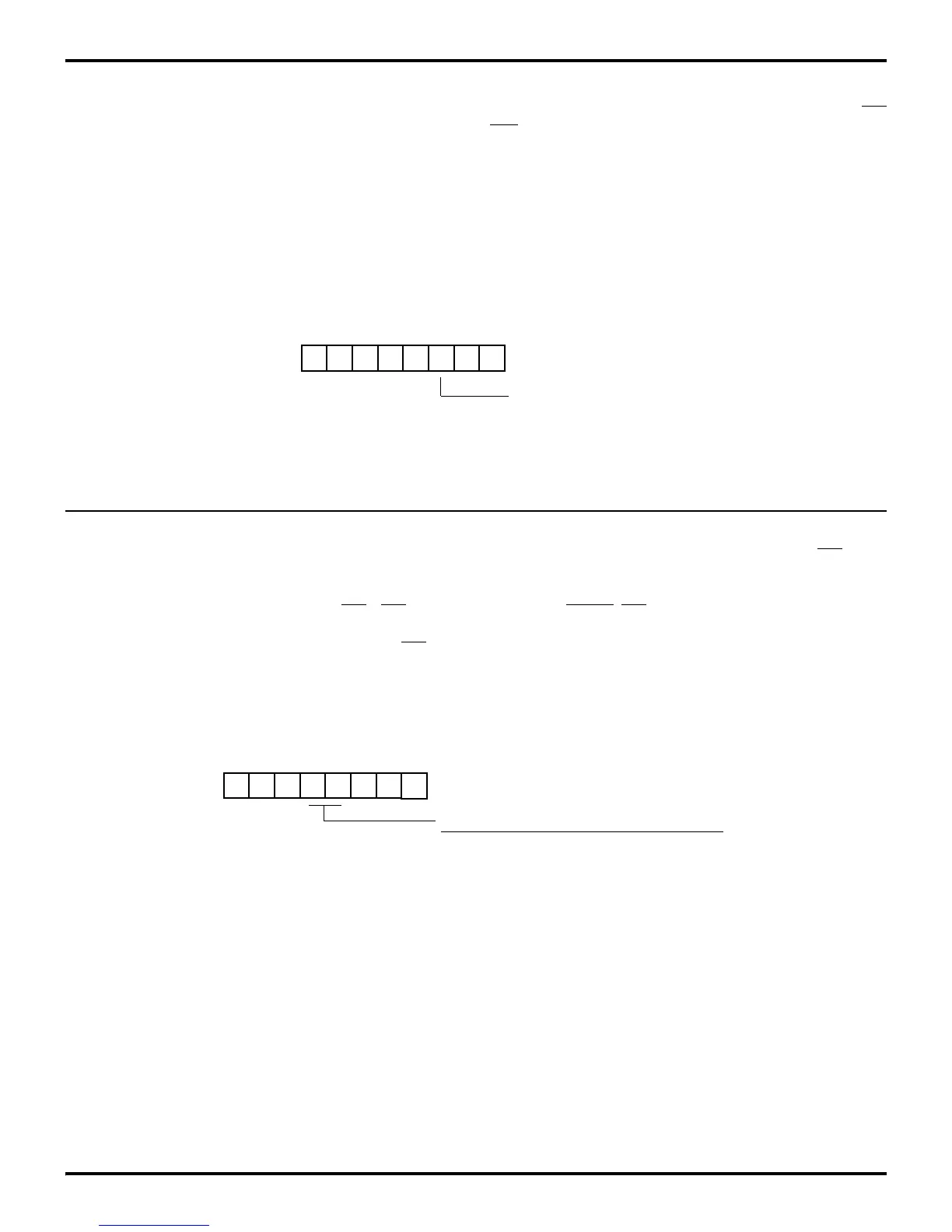
Figure 10-3. Z8 Stack Selection
D7 D6 D5 D4 D3 D2 D1 D0
(Write-Only)
Port 0-1 Register
Register F8H (P01M)
Z8 Stack Selection
0 = External
1 = Internal
Figure 10-4. Port 3 Data Memory Operation
D7 D6 D5 D4 D3 D2 D1 D0
(Write-Only)
Bits Configuration
00 P33 = Input P34 = Output
01 P33 = Input P34 = /DM
Port 3 Mode Register
Register F7H (P3M)
10 P33 = Input P34 = /DM
11 P33 = /DAV1/RDY1 P34 = RDY1//DAV1

 Loading...
