Z8 Microcontrollers
ZiLOG External Interface
UM001601-0803 10-9
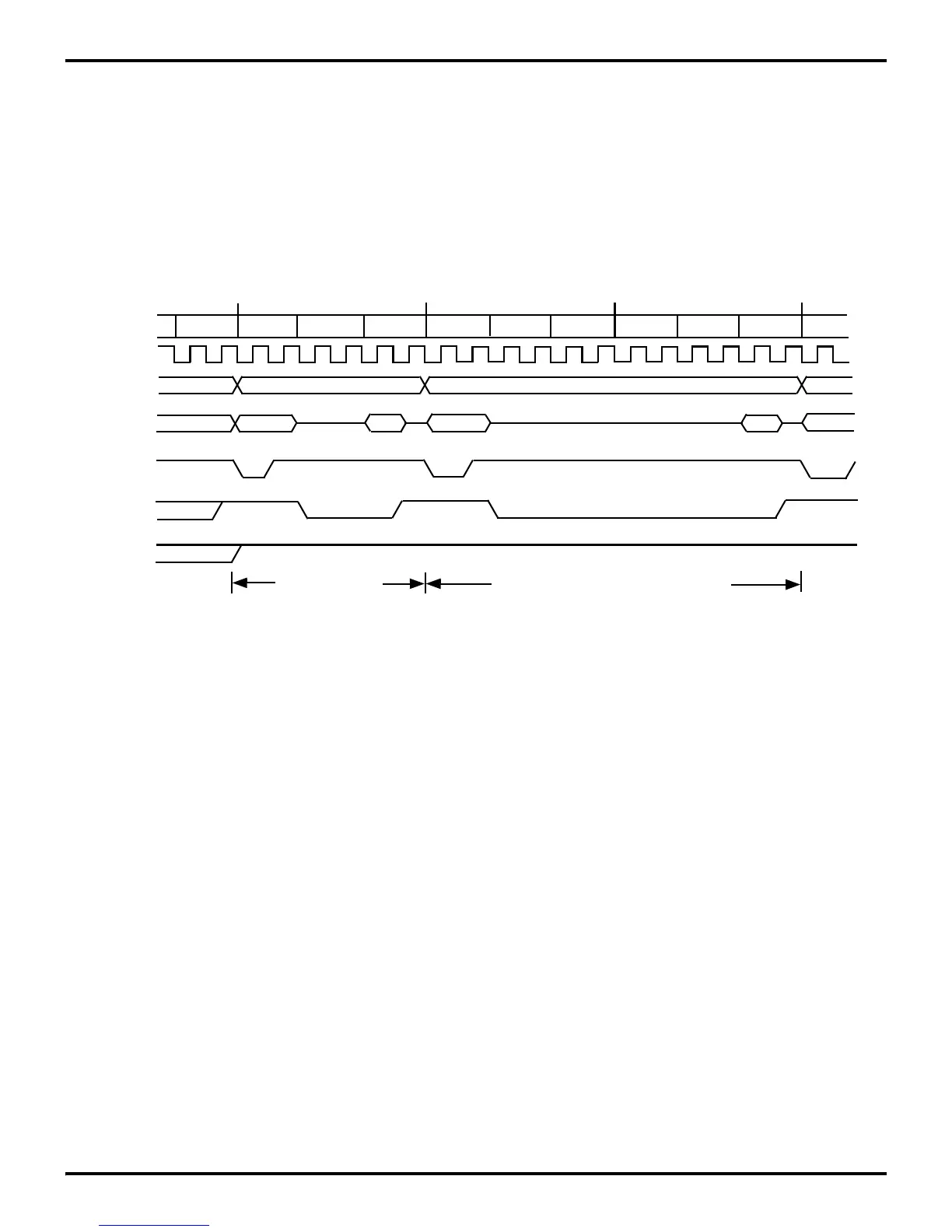
10.8 INSTRUCTION TIMING
The High throughput of the Z8 is due, in part, to the use of an
instruction pipeline, in which the instruction fetch and execution
cycles are overlapped. During the execution of the current in
-
struction, the opcode of the next instruction is fetched. Instruc-
tion pipelining is illustrated in Figure 10-10.
Figures 10-10 and 10-11 show typical instruction cycle timing
for instructions fetched from memory. For those instructions that
require execution time longer than that of the overlapped fetch,
or reference program or data memory as part of their execution,
the pipe must be flushed.
Figures 10-10 and 10-11 assume the XTAL/2 clock mode is
selected.
Figure 10-10. Instruction Cycle Timing (One-Byte Instructions)
T1 T2
T3
T3
T1
/DS
/AS
R/W
T1
T2
T2
Fetch 1st Byte
T3
M1
M2
M3
A15-A8
A15-A8
A15-A8
A7-A0
A7-A0
A7-A0
A7-A0
A7-A0
Fetch 1st Byte Of Next Instruction
* Port inputs are strobed during T2, which is two internal system clocks
before the execution cycle of the current installation
Clock

 Loading...
