Z8 Microcontrollers
I/O Ports ZiLOG
5-4 UM001601-0803
5.2 PORT 0 (Continued)
5.2.2 Read/Write Operations
In the nibble I/0 Mode, Port 0 is accessed as general-purpose
register P0 (00H) with ERF Bank set to 0. The port is written by
specifying P0 as an instruction's destination register. Writing to
the port causes data to be stored in the port's output register.
The port is read by specifying P0 as the source register of an in-
struction. When an output nibble is read, data on the external
pins is returned. Under normal loading conditions this is equiv
-
alent to reading the output register. However, for Port 0 outputs
defined as open–drain, the data returned is the value forced on
the output by the external system. This may not be the same as
the data in the output register. Reading a nibble defined as input
also returns data on the external pins. However, input bits under
handshake control return data latched into the input register via
the input strobe.
The Port 0–1 Mode resister bits D
1
D
0
and D
7
D
6
are used to con-
figure Port 0 nibbles. The lower nibble (P0
0
–P0
3
) can be defined
as inputs by setting bits D
1
to 0 and D
0
to 1, or as outputs by set-
ting both D
1
and D
0
to 0. Likewise, the upper nibble (P0
4
–P0
7
)
can be defined as inputs by setting bits D
7
to 0 and D
6
to 1, or as
outputs by setting both D
6
and D
7
to 0 (Figure 5-5).
5.2.3 Handshake Operation
When used as an I/0 port, Port 0 can be placed under handshake
control by programming the Port 3 Mode register bit D
2
to 1. In
this configuration, handshake control lines are DAV
0
(P3
2
) and
RDY
0
(P3
5
) when Port 0 is an input port, or RDY
0
(P3
2
) and
DAV
0
(P3
5
) when Port 0 is an output port. (See Figure 5-6)
Handshake direction is determined by the configuration (input or
output) assigned to the Port 0 upper nibble, P0
4
–P0
7
. The lower
nibble must have the same I/0 configuration as the upper nibble
to be under handshake control. Figure 5-3 illustrates the Port 0
upper and lower nibbles and the associated handshake lines of
Port 3.
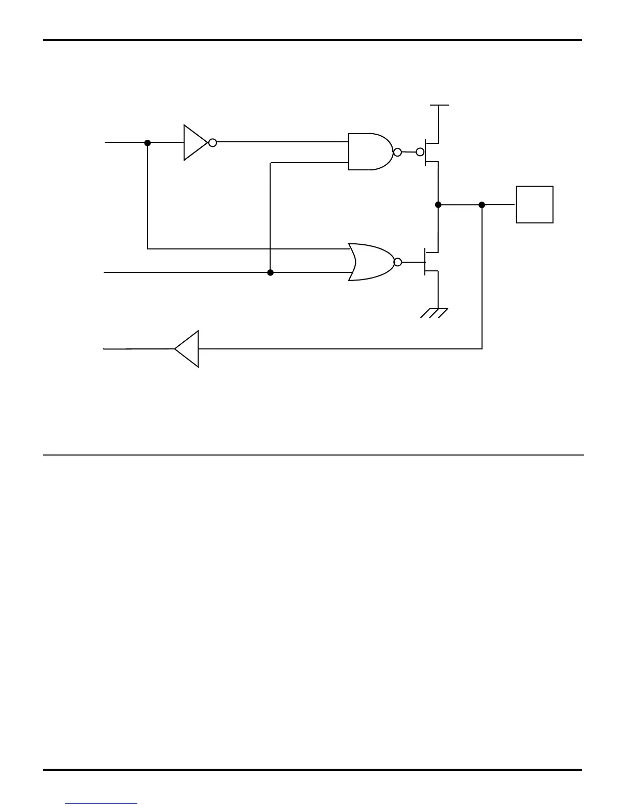
Figure 5-4. Port 0 Configuration with TTL Level Shifter
OEN
PIN
OUT
IN
TTL Level Shifter