UM001601-0803 9-1
USER’S MANUAL
CHAPTER 9
SERIAL I/O
9.1 UART INTRODUCTION
Select Z8 MCU
®
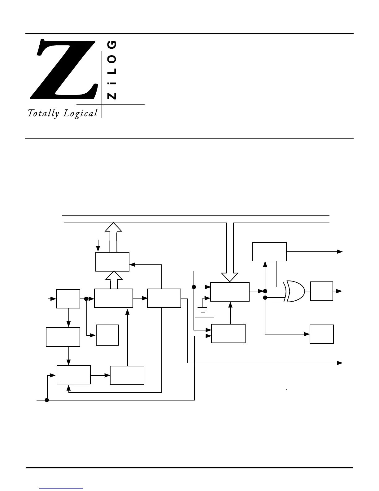
microcontrollers contain an on-board full-du-
plex Universal Asynchronous Receiver/Transmitter (UART) for
data communications. The UART consists of a Serial I/O Regis
-
ter (SIO) located at address F0H, and its associated control logic
(Figure 9-1). The SIO is actually two registers, the receiver buff
-
er and the transmitter buffer, which are used in conjunction with
Counter/Timer T0 and Port 3 I/O lines P30 (input) and P37 (out
-
put). Counter/Timer T0 provides the clock input for control of
the data rates.
Figure 9-1. UART Block Diagram
Stop
Bit Detect
Transmitter
Shift Register
÷6
Parity
Gan
Serial
Out
Char
Detect
Receiver
Buffer
Receiver
Shift Register
Serial
In
Start
Bit Detect
Clock
Control
Parity
Check
Shift
Clock
Shift
Clock
÷16
Transfer
Stop
Start
Write FOH
RESET
Read FOH
Mark
Serial I/O Clock (From T0)
IRQ
4
Internal Data Bus
IRQ
3
P3
7
P3
0

 Loading...
