Z8 Microcontrollers
ZiLOG Interrupts
UM001601-0803 7-7
7.4.3 Interrupt Request (IRQ) Register Initialization
IRQ (Figure 7-9) is a read/write register that stores the interrupt
requests for both vectored and polled interrupts. When an inter
-
rupt is made on any of the six, the corresponding bit position in
the register is set to 1. Bit 0 to bit 5 are assigned to interrupt re
-
quests IRQ0 to IRQ5, respectively.
Whenever Power-On Reset (POR) is executed, the IRQ resister
is reset to 00H and disabled. Before the IRQ register will accept
requests, it must be enabled by executing an ENABLE INTER
-
RUPTS (EI) instruction.
Note: Setting the Global Interrupt Enable bit in the Interrupt
Mask Register (IMR, bit 7) will not enable the IRQ. Execution
of the EI instruction is required (Figure 7-10).
For polled processing, IRQ must still be initialized by an EI in-
struction.
To properly initialize the IRQ register, the following code is pro-
vided:
Note: IRQ is always cleared to 00Hex and is read only until the
1st EI instruction which enables the IRQ to be read/write.
CLR IMR //make sure disabled vectored interrupts
EI //enable IRQ register otherwise read only.
//not needed if interrupts were previously
enabled.
DI //disable interrupt heading.
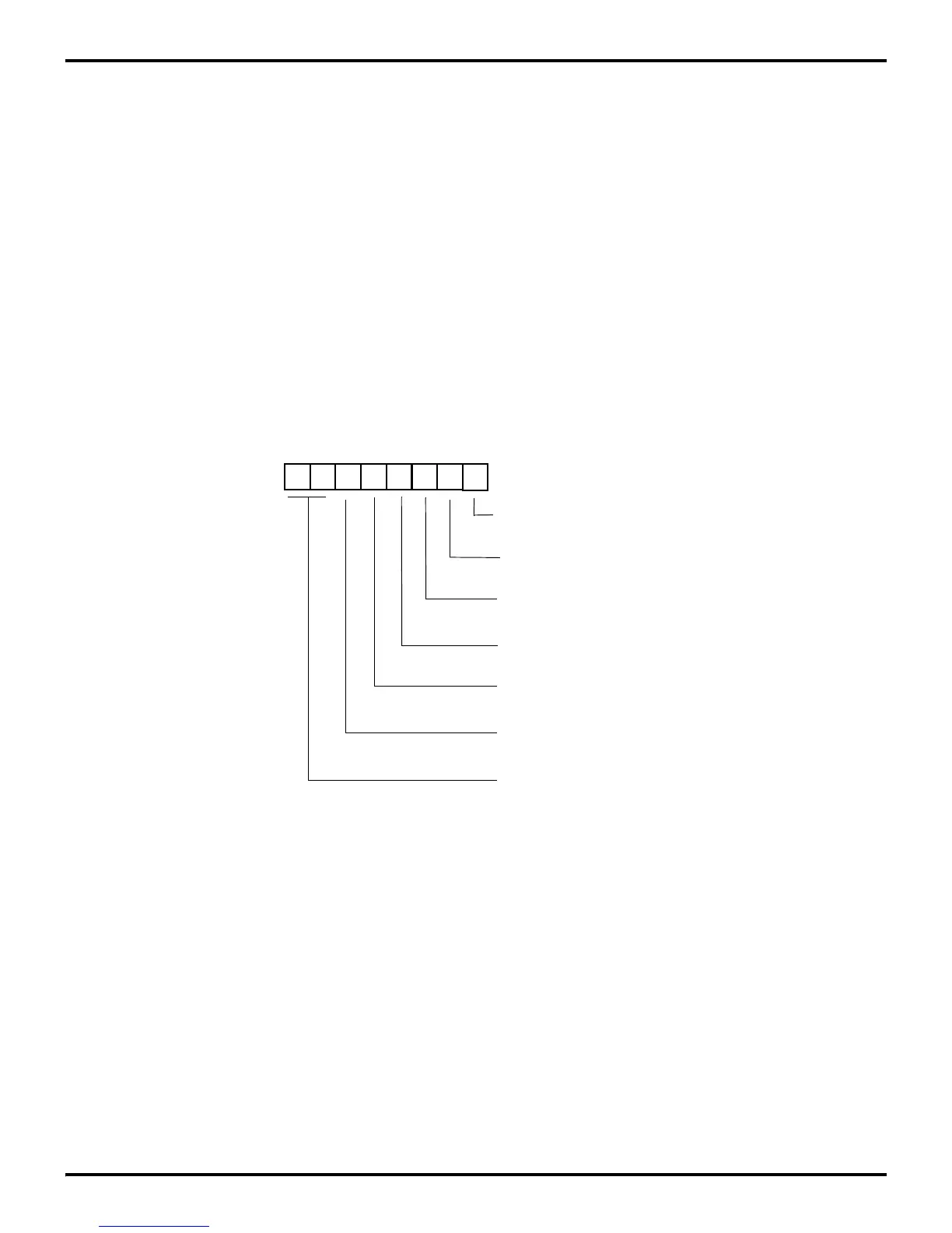
Figure 7-9. Interrupt Request Register
D7 D6 D5 D4 D3 D2 D1 D0
(Read/Write)
Reserved /Int Edge Select
Interrupt Request Register (IRQ)
Register FAH
0 = IRQ0 RESET
1 = IRQ0 SET
0 = IRQ1 RESET
1 = IRQ1 SET
0 = IRQ2 RESET
1 = IRQ2 SET
0 = IRQ3 RESET
1 = IRQ3 SET
0 = IRQ4 RESET
1 = IRQ4 SET
0 = IRQ5 RESET
1 = IRQ5 SET
 Loading...

