Z8 Microcontrollers
Interrupts ZiLOG
7-8 UM001601-0803
7.4 INTERRUPT INITIALIZATION (Continued)
IMR is cleared before the IRQ enabling sequence to insure no
unexpected interrupts occur when EI is executed. This code se
-
quence should be executed prior to programming the application
required values for IPR and IMR.
Note: IRQ bits 6 and 7 are device dependent. When reserved,
the bits are not used and will return a 0 when read. When used as
the Interrupt Edge select bits, the configuration options are as
show in Table 7-4.
The proper sequence for programming the interrupt edge select
bits is (assumes IPR and IMR have been previously initialized):
Tab le 7-4. IRQ Register Configuration
IRQ Interrupt Edge
D7 D6 P31 P32
0 0 F F
0 1 F R
1 0 R F
1 1 R/F R/F
Notes:
F = Falling Edge
R = Rising Edge
DI ;Inhibit all interrupts
until input edges are
configured
OR IRQ,#XX 000000B ;Configure interrupt
do not disturb
edges as needed -
IRQ 0-5.
EI ;Re-enable interrupts.
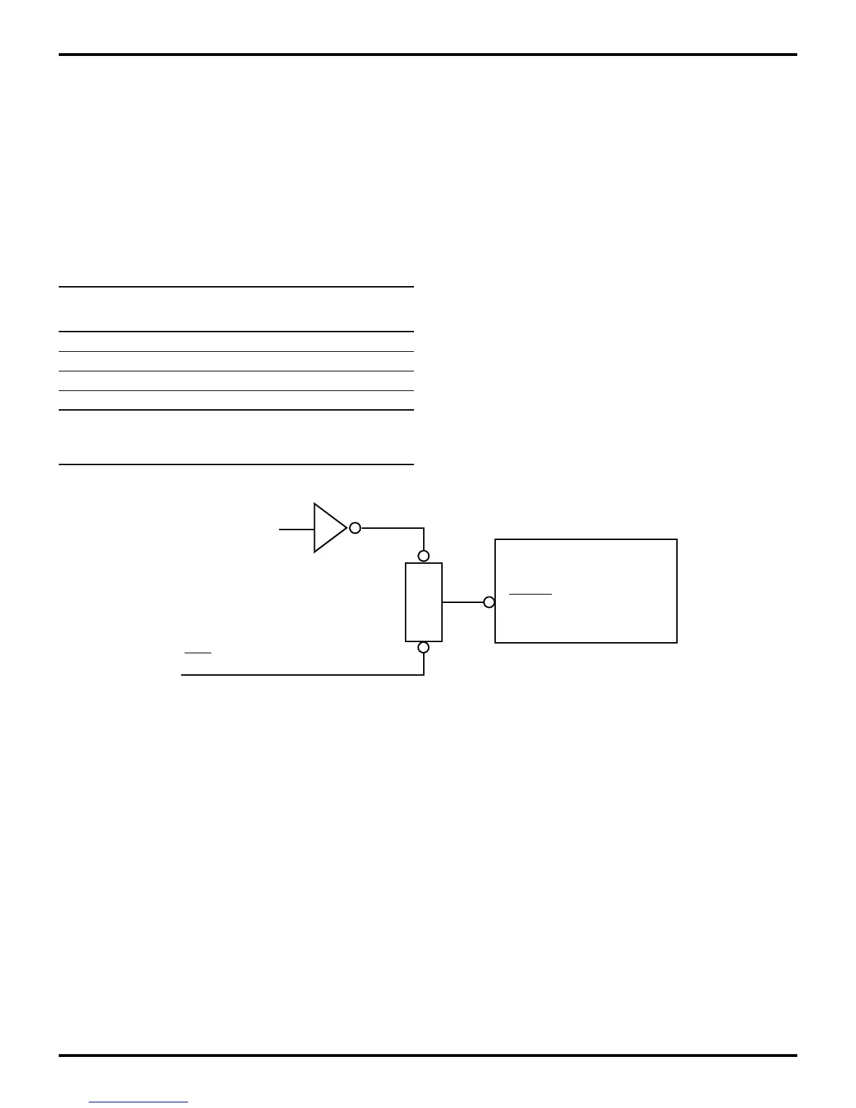
Figure 7-10. IRQ Reset Functional Logic Diagram
S
Interrupt Request Register
(IRQ, FAH)
RESET
El Instruction
POR
R