Z8 Microcontrollers
Counter/Timers ZiLOG
6-8 UM001601-0803
It is suggested that P31 be configured as an input line by setting
P3M Register bit 5 to 0, although T
IN
is still functional if P31 is
configured as a handshake input.
Each High-to-Low transition on T
IN
generates an interrupt re-
quest IRQ2, regardless of the selected T
IN
mode or
the enabled/disabled state of T1. IRQ2 must therefore be masked
or enabled according to the needs of the application.
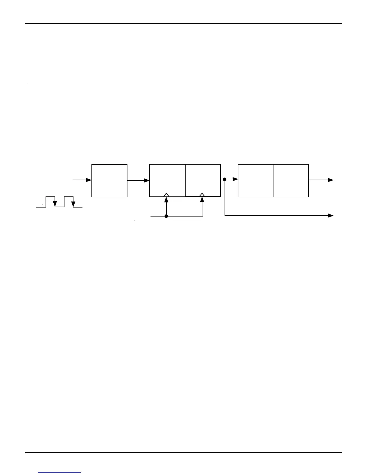
6.5.1 External Clock Input Mode
The T
IN
External Clock Input Mode (TMR bit 5 and bit 4 both
set to 0) supports counting of external events, where an event is
considered to be a High-to-Low transition on T
IN
(Figure 6-15).
Note: See the product data sheet for the minimum allowed T
IN
external clock input period (T
P
T
IN
).
Figure 6-15. External Clock Input Mode
D
P3
1
Internal
IRQ
2
TMR
T
IN
Clock
D
PRE1
T1
IRQ
5
D
5
- D
4
= 00
Clock
 Loading...

