UM001601-0803 10-1
USER’S MANUAL
CHAPTER 10
EXTERNAL INTERFACE
10.1 INTRODUCTION
The Z8
can be a microcontroller with 20 pins for external mem-
ory interfacing. The external memory interface on the Z8 is gen-
erally for either RAM or ROM. This is only available for devices
featuring Port 0, Port 1, R/
W, DM, AS, and DS. Please refer to
specific product specifications for availability of these features.
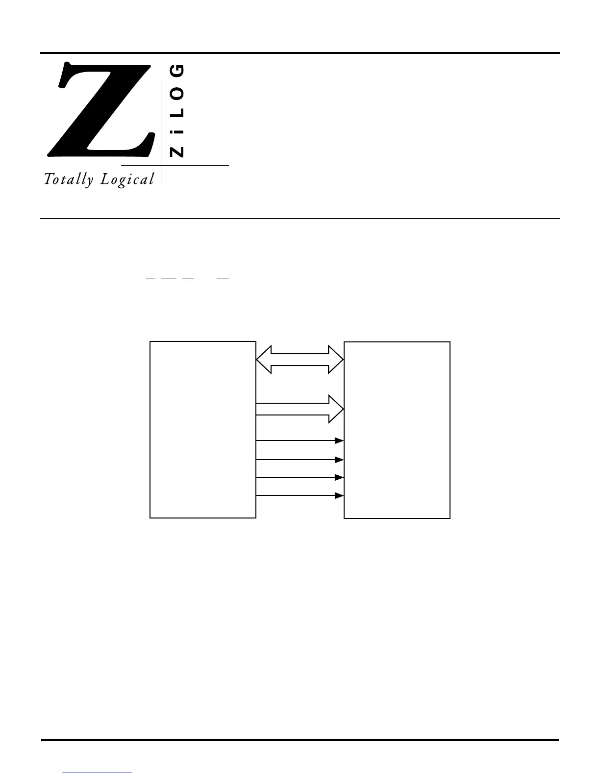
The Z8 has a multiplexed external memory interface. In the mul-
tiplexed mode, eight pins from Port 1 form an Address/Data Bus
(AD7-AD0), eight pins from Port 0 form a High Address Bus
(A15-A8). Three additional pins provide the Address Strobe,
Data Strobe, and the Read/Write Signal. Figure 10-1 shows the
Z8 external interface pins.
Figure 10-1. Z8 External Interface Pins
External
Z8 MCU
Program/Data
64 Kbytes
Each
(Port 1) AD7 - AD0
(Port 0) AD15 - AD8
/AS
/DS
R//W
/DM

 Loading...
