Z8 Microcontrollers
I/O Ports ZiLOG
5-22 UM001601-0803
5.7 I/O PORT RESET CONDITIONS
5.7.1 Full Reset
After a hardware reset, Watch-Dog Timer (WDT) reset, or a
Power-On Reset (POR), Port Mode Registers P01M, P2M, and
P3M are set as shown in Figures 5-27 through 5-22. Port 2 is
configured for input operation on all bits and is set for open-
drain (Figure 5-29). If push-pull outputs are desired for Port 2
outputs, remember to configure them using P3M. Please note
that a WDT time-out from Stop-Mode Recovery does not do a
full reset. Certain registers that are not reset after Stop-Mode Re
-
covery will not be reset.
For the condition of the Ports after Stop-Mode Recovery, please
refer to specific device product specifications. In some cases, the
Z8 has the P01M, P2M, and P3M control register set back to the
default condition after reset while others do not.
All special I/O functions of Port 3 are inactive, with P33–P30 set
as inputs and P37–P34 set as outputs (Figure 5-29).
Note: Because the types and amounts of I/O vary greatly among
the Z8 family devices, the user is advised to review the selected
device's product specifications for the register default state after
reset.
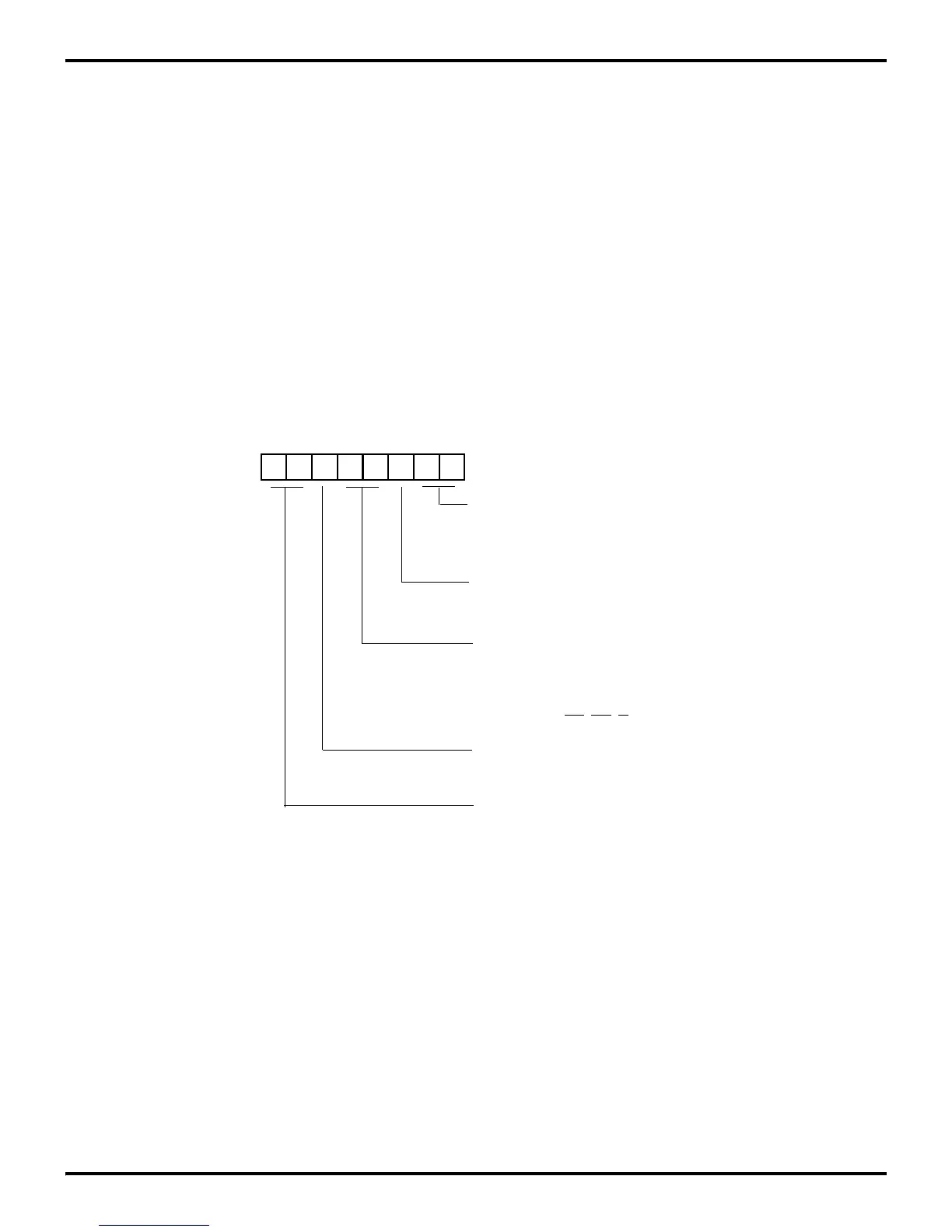
Figure 5-27. Port 0/1 Reset
0 1 0 0 1 1 0 1
(Write-Only)
01 = Input
1X = A
8
- A
11
Stack Selection
0 = External
P0
0
- P0
3
Mode
00 = Output
Port 0-1 Mode Register (P01M)
Register F8H
01 = Byte Output
1 = Internal
External Memory Timing
Normal = 0
Extended = 1
P0
4
- P0
7
Mode
Output = 00
Input = 01
A
12
- A
15
= 1X
10 = AD
0
- AD
7
00 = Byte Output
P
10
- P
17
Mode
A
8
- A
15
, AS, DS, R/W
11 = High Impedance AD
0
- AD
7,