Z8 Microcontrollers
ZiLOG Clock
UM001601-0803 3-5
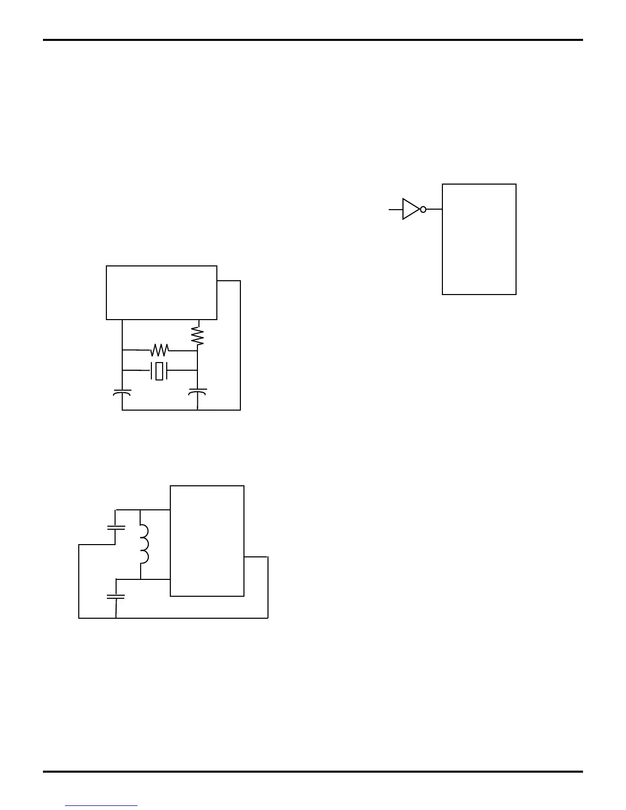
3.4.4 Crystals and Resonators
Crystals and ceramic resonators (Figure 3-7) should have the
following characteristics to ensure proper oscillator operation:
Depending on operation frequency, the oscillator may require
the addition of capacitors C1 and C2 (shown in Figures 3-7). The
capacitance values are dependent on the manufacturer’s crystal
specifications.
In most cases, the R
D
is 0 Ohms and R
F
is infinite. It is deter-
mined and specified by the crystal/ceramic resonator manufac-
turer. The R
D
can be increased to decrease the amount of drive
from the oscillator output to the crystal. It can also be used as an
adjustment to avoid clipping of the oscillator signal to reduce
noise. The R
F
can be used to improve the start-up of the crys-
tal/ceramic resonator. The Z8 oscillator already has an internal
shunt resistor in parallel to the crystal/ceramic resonator.
It is recommended in Figures 3-7, 3-8, and 3-9 to connect the
load capacitor ground trace directly to the V
SS
(GND) pin of the
Z8
®
. This ensures that no system noise is injected into the Z8
clock. This trace should not be shared with any other compo
-
nents except at the V
SS
pin of the Z8.
In some cases, the Z8 XTAL1 pin also functions as one of the
EPROM high-voltage mode programming pins or as a special
factory test pin. In this case, applying 2 V above V
CC
on the
XTAL1 pin will cause the device to enter one of these modes.
Since this pin accepts high voltages to enter these respective
modes, the standard input protection diode to V
CC
is not on
XTAL1. It is recommended that in applications where the Z8 is
exposed to much system noise, a diode from XTAL1 to V
CC
be
used to prevent accidental enabling of these modes. This diode
will not affect the crystal/ceramic resonator operation.
Please note that a parallel resonant crystal or resonator data sheet
will specify a load capacitor value that is the series combination
of C
1
and C
2
, including all parasitics (PCB and holder).
Crystal Cut AT (crystal only)
Mode Parallel, Fundamental Mode
Crystal Capacitance <7pF
Load Capacitance 10pF < CL < 220 pF,
15 typical
Resistance 100 ohms max
Figure 3-7. Crystal/Ceramic Resonator Oscillator
Figure 3-8. LC Clock
XTAL2
Z8
V
SS
XTAL1
C1
C2
R
F
R
D
XTAL2
Z8
V
SS
XTAL1
C1
C2
L
Figure 3-9. External Clock
XTAL2
Z8
V
SS
XTAL1