Z8 Microcontrollers
ZiLOG Counter/Timers
UM001601-0803 6-7
6.5 T
IN
MODES
The Timer Mode Register TMR (F1H) (Figure 6-13) is used in
conjunction with the Prescaler Register PRE1 (F3H) (Figure 6-
14) to configure P31 as T
IN
. T
IN
is used in conjunction with T1
in one of four modes:
• External Clock Input
• Gated Internal Clock
• Triggered Internal Clock
• Retriggerable Internal Clock
Note: The T
IN
mode is restricted for use with timer 1 only. To
enable the T
IN
mode selected (via TMR bits 4- 5), bit 1 of PRE1
must be set to 0.
The counter/timer clock source must be configured for external
by setting the PRE1 Register bit 2 to 1. The Timer Mode Regis
-
ter bit 5 and bit 4 can then be used to select the desired T
IN
oper-
ation.
For T1 to start counting as a result of a T
IN
input, the Enable
Count bit (bit 3 in TMR) must be set to 1. When using T
IN
as an
external clock or a gate input, the initial values must be loaded
into the down counters by setting the Load bit (bit 2 in TMR) to
a 1 before counting begins. In the descriptions of T
IN
that follow,
it is assumed the programmer has performed these operations.
Initial values are automatically loaded in Trigger and Retrigger
modes so software loading is unnecessary.
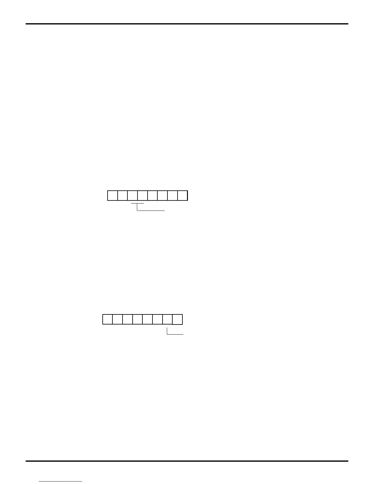
Figure 6-13. Timer Mode Register (T
IN
Operation)
D5 D4
(Read/Write)
Timer Mode Register (TMR)
Register F1H
(Retriggerable)
(Non-retriggerable)
Trigger Input = 10
T
IN
= Modes:
External Clock Input = 00
Gate Input = 01
Trigger Input = 11
Figure 6-14. Prescaler 1 Register (T
IN
Operation)
D7 D6 D5 D4 D3 D2 D1 D0
(Write-Only)
1 = T
1
Internal Disable T
IN
Mode
Clock Source
0 = T
1
External Enable T
IN
Mode
Prescaler 1 Register (PRE1)
Register F3H
 Loading...

