Z8 Microcontrollers
ZiLOG I/O Ports
UM001601-0803 5-13
5.5 PORT 3
5.5.1 General Port I/O
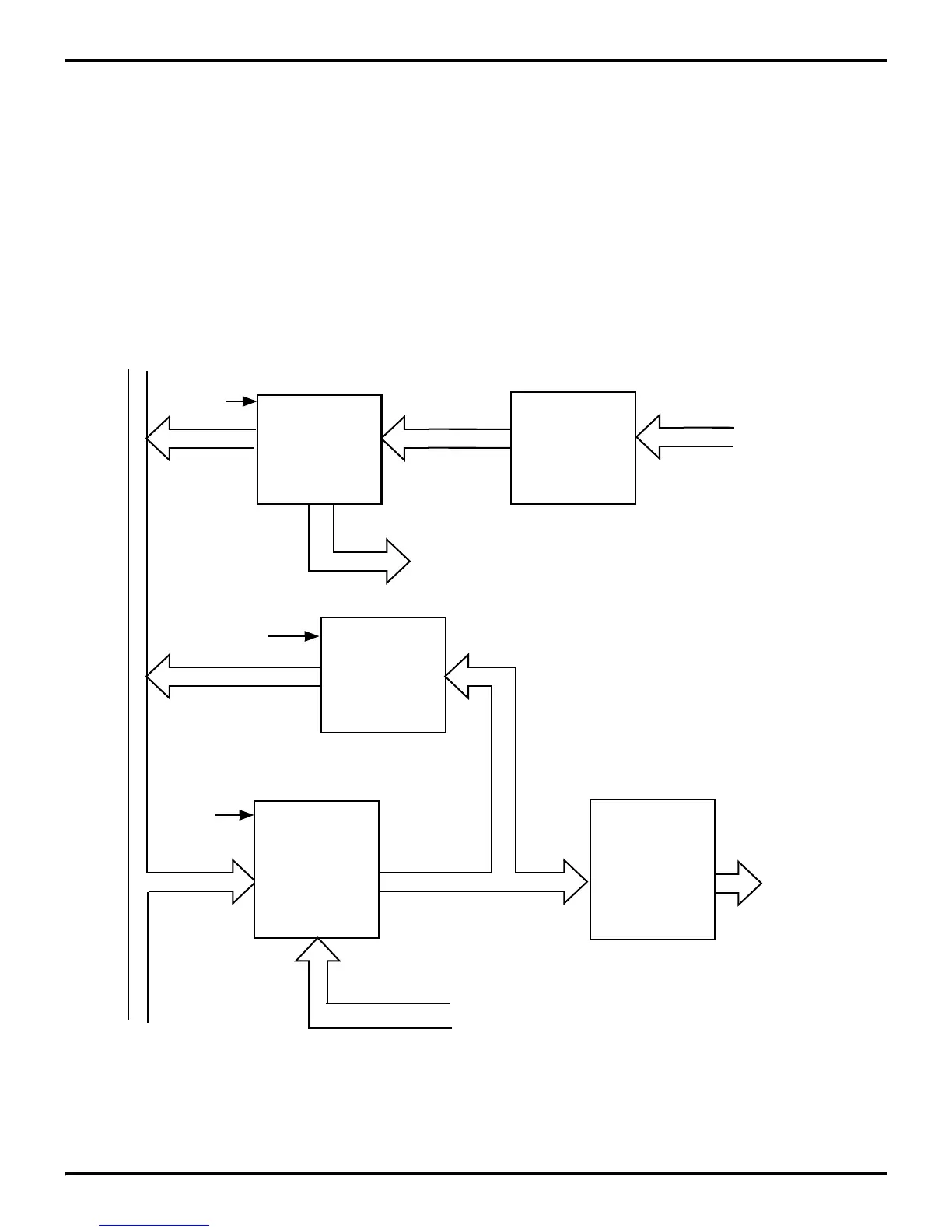
Port 3 differs structurally from Port 0, 1, and 2. Port 3 lines are
fixed as four inputs (P33–P30) and four outputs (P37–P34) Port
3 does not have an input and output register for each bit. Instead,
all the input lines have one input register, and all the output lines
have an output register. Port 3 can be a CMOS- or TTL- compat
-
ible I/O port. Under software control, the lines can be configured
as special control lines for handshake, comparator inputs, SPI
control, external memory status, or I/O lines for the on-board se
-
rial and timer facilities. Figure 5-17 is a generic block diagram
of Port 3.
The inputs can be Schmitt-triggered, level-shifted, or single-trip
point buffered. In some cases, the Z8 may have auto latches
hardwired on certain Port 3 inputs and Low-EMI capabilities on
the outputs. Please refer to specific product specifications for ex
-
act input/output buffer type features. Please refer to the section
on counter/timers, Stop-Mode Recovery, serial I/O, compara
-
tors, and interrupts for more information on the relationships of
Port 3 to that feature.
Figure 5-17. Port 3 Block Diagram
Input
Buffer
Input
Register
Output
Buffer
Output
Register
Output
Register
Write
Port
Read
Port
4
4
4
4
4
4
4
4
Internal
Bus
From Timer,
Handshake Logic,
or Serial I/O
To Interrupt Timer,
Handshake Logic,
or Serial I/O
Port
Output
Lines
P3
4
- P3
7
Port
Input
Lines
P3
0
- P3
3
Read
Port
Input
Buffer
Output
Buffer
Output
Register
Output
Buffer
Data
Return

 Loading...
