GDP-32
II
INSTRUCTION MANUAL
October 2002 Section 12, Page 32
12.17 METHOD TO FIELD-CHECK MAGNETIC SENSORS
It is possible to field check the operation of an antenna by using the GDP calibrator as a signal
source as follows:
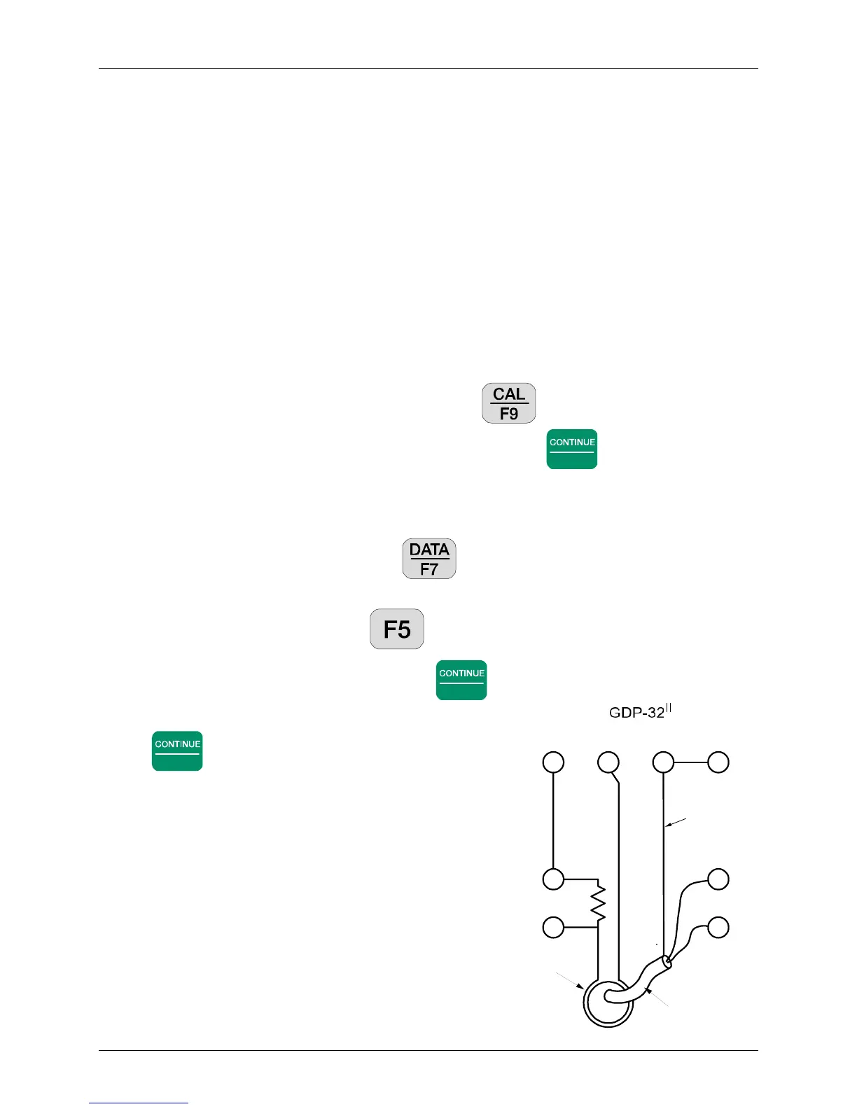
1. Connect a 1 K ohm resistor between the Channel-1 Black and Red input terminals.
2. Take a piece of wire or test lead and make a single turn around the antenna case as shown
on the diagram. Connect one end of the wire to the Negative CALIBRATE output and
the other end to the Negative (Black) input terminal for Channel-1.
3. Connect a test lead from the Red CALIBRATE output to Channel-1 Red Input.
4. Connect the coil output cable to the Channel-2 inputs as shown on the diagram.
5. Turn on the receiver and enter the CSAMT program. Set Channel-1 to Ex and
Channel-2 to Hy with the antenna number set to 1.
6. Set the frequency to the lowest value you want to check - for instance 0.125 Hz.
7. Turn on the antenna.
8. Enter the calibrate program by pressing the key. Then press 3) Auto
System Check and then press 2) External. Press
Enter
to finish setting up the
external calibrate system, and to begin taking data.
9. The program will automatically acquire data for each frequency, for example 0.125 Hz
through 8192 Hz.
10. Enter the data mode by pressing the key. Check to see the block number of the
first data acquired. Then return to the last data block.
11. Enter the plot mode by pressing . Press 3) Magnitude Plot.
12. Enter the starting block number and press
Enter
.
13. Enter the starting channel number = 2 and press
Enter
.
14. The plot that you get will be the magnitude plot for
the coil being tested. It should have the same shape
as the calibration done in our test facility.
15. If you want to look at the difference between a
calibrate stored in the receiver and the response
from this test, go back to step 4 and set the antenna
number to the proper value for the antenna under
test. Follow the same steps as outlined above. The
result when you plot the data will be a straight line.
Note: The reason for monitoring the current through the
1 K ohm resistor is to make sure that the signal level is
constant over the frequency range being tested.
Red
CH2
Black
1K ohm
CAL+ CAL- COM CASE
Cable from TEM/3
or ANT/* antennas
Antenna with
one turn of wire
around middle
Shield
Red
CH1
Black