GDP-32
II
USER'S NOTES
Section 18, Page 5 May 2002
18.6 TRANSMITTER CONTROL INTERFACE
The GGT series transmitters use a twenty milliamp control signal with a rise and fall time of less
than one microsecond. There are two control signals used; Transmitter on/off and Polarity.
1. TRANSMITTER ON/OFF. This signal is used in the time domain mode to turn off the
transmitter when needed depending on the duty cycle required.
2. POLARITY. This signal controls the output polarity of the transmitter. When the signal
is supplied the transmitter reverses the output polarity from the rest state.
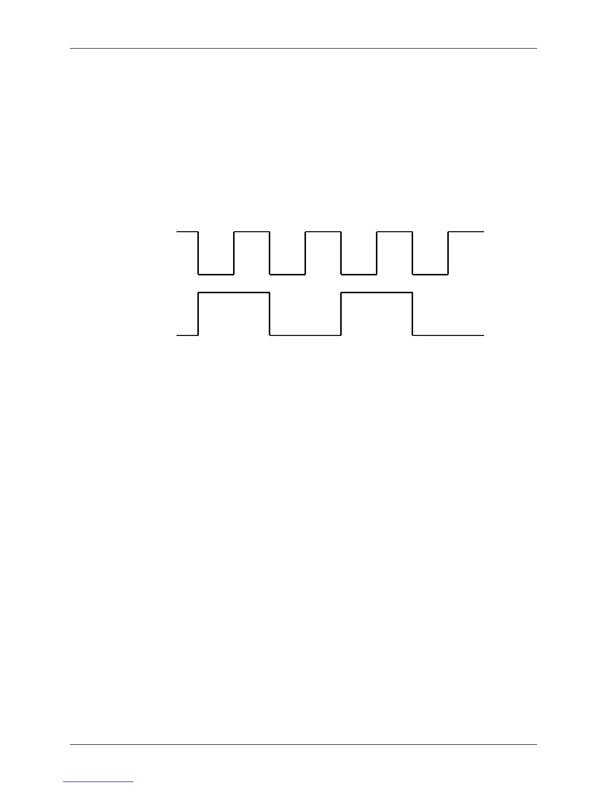
The timing diagram below shows the relationship between the two signals for a fifty percent duty
cycle.
Presently we use a National Semiconductor chip to provide the drive for the transmitter from
both the transmitter controller and the receiver. This MM88C3ON chip is used with either a 180
ohm or 560 ohm resistor in the output, depending on whether it is interfaced to 5 volt or 12 volt
logic. This limits the current to a maximum of twenty milliamps in the drive circuits. The speed
of the chip is more than sufficient to provide the proper drive.
Transmitter Control MS Connector
Polarity: A
Ground: B, E (Need to be shorted together)
Transmitter ON/OFF: C (With no connection, default is ON)
Duty cycle: D
Transmitter
ON/OFF
(Duty Cycle)
Polarity
(Period)
ON
+