RECEIVER SETUP
Section 6, Page 27 May 2002
6.3 MEASURING CONTACT RESISTANCE
After completing the system calibration, set up the electrode array and connect the field wires to
the receiver analog input jacks (Refer to the different survey program sections for instructions on
connecting wires to the receiver.)
Zonge Engineering recommends measuring the contact resistance between the potential
electrodes (pots) and the ground before acquiring data. A contact resistance measurement
provides information on the status of the pots. For example, an “open” contact resistance
measurement on a pot may indicate that the pot has not been connected, is drying out, or has
been dislodged from the ground.
NOTE: Remember to measure the contact resistance at each new receiver array location.
Make electrode resistance measurements from the Data Acquisition Screen of the appropriate
survey program.
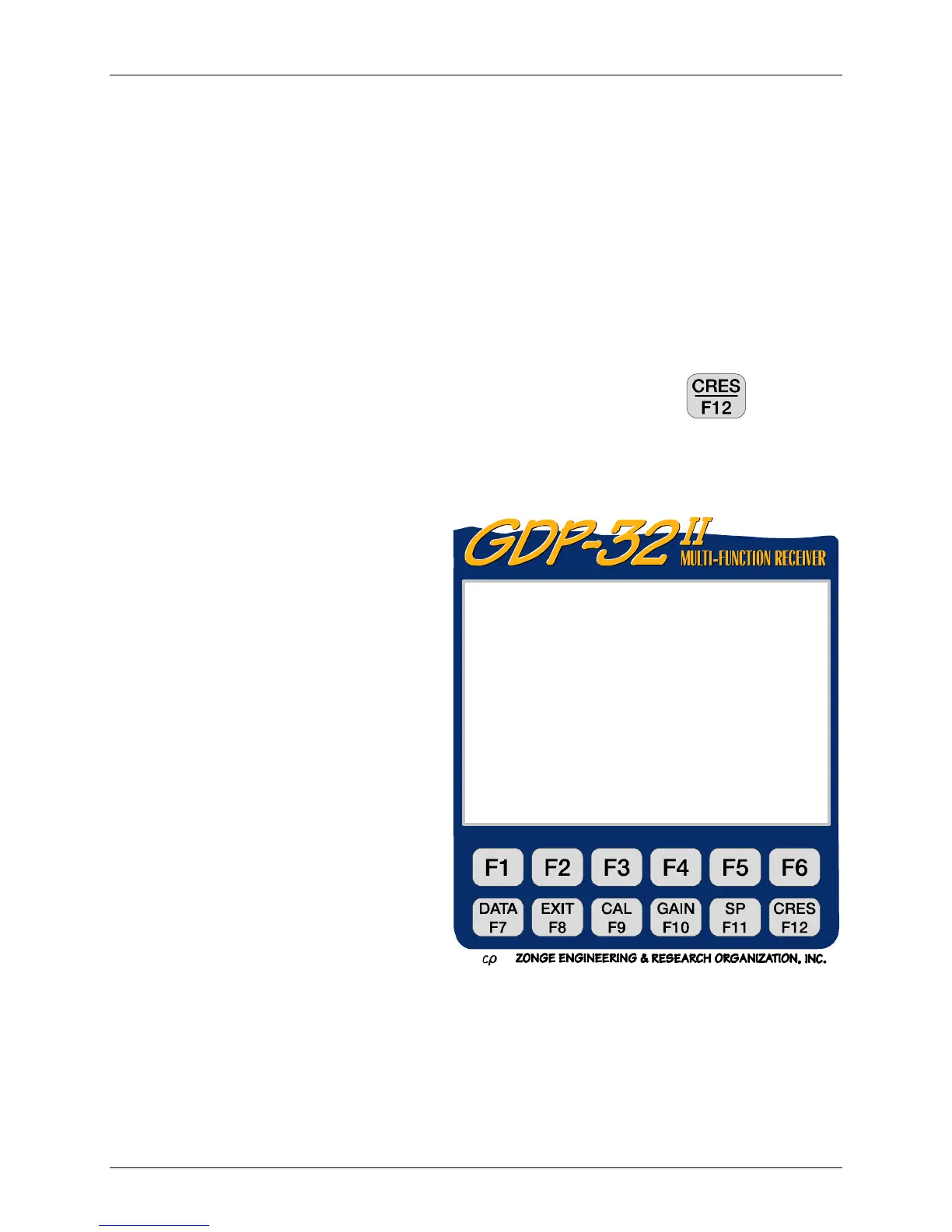
1. With the transmitter off and all field wires attached to the receiver, press
.
NOTE: For methods using low signal levels such as CSAMT, it is often unnecessary to turn
the transmitter off before to making contact resistance measurements.
2. The receiver sets all gains to unity and
offsets any SP potential. It then
calculates the sum of the contact
resistance for both pots of each dipole.
Each channel takes about two seconds.
The sound of relays clicking can be
heard for each active Analog Board.
The contact resistance for each channel
is then displayed on the screen, as
shown in the screen below.
In the following screen all channels except
channels 1 and 2 show reasonable contact
resistances (i.e. in the 1 kΩ to 10 kΩ
range.) These values are the total dipole
resistance. Channels 4 and 5 show
“Open”, which indicates open circuits (the
pot common to dipoles 4 and 5 is not
placed properly, broken wire, faulty
connection, etc.), or the contact resistance
is in excess of 100 kΩ. If the channel is
turned off or is disconnected, no value is
displayed.
0190 RPIP0613 11.7 08 Jan 18 10:06:13
Survey D-D
Tx 1Rx 700N OUT
1Hz 1CyclesTxCurr 1
CH N CRES
1ON 1 18.3K
2ON 2 1.06K
3ON 3 Open
4ON 4 Open
CONT-Set gains, ESC-Prev Menu