RECEIVER SETUP
Section 6, Page 7 May 2002
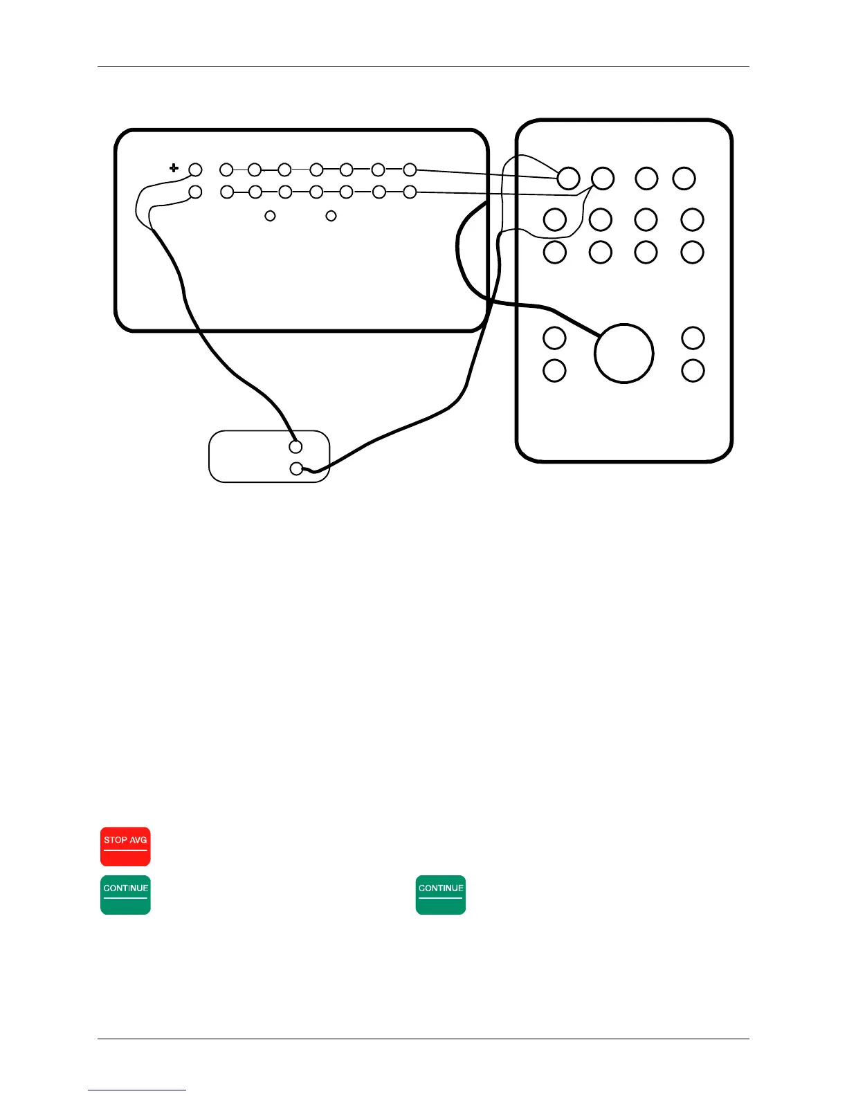
Figure 6.1 - Wiring for an external calibration – large case with Patch Panel using an isolation
amplifier on the reference channel.
Use an internal calibration for standard operations. Use an external calibration if there are active
auxiliary electronics such as preamplifiers or isolation amplifiers whose effects must be included
in the calibration, or if the analog input section needs to be checked.
After selecting an internal or external signal source, the cursor goes to the end of the third line on
the display, where the display reads:
ICal = 1v
This is the “calibration signal voltage” (i.e. the amplitude of the voltage signal that is supplied by
the Calibration Board for calibration.) The default selection amplitude is 1 volt. Generally
speaking, there will be no need to change it. The Instruction line displays:
Change Calibration voltage or press
CONTINUE to proceed, ESCAPE to abort.
Escape
exits the calibration mode and returns to the Data Acquisition Screen.
Enter
begins an automatic calibration. Press
Enter
. The Instruction Line reads:
CONT when gains are set, ESCAPE to exit.
1 2 3 4 5 6 7 8
PATCH PANEL
ANALOG I/O PANEL
GND CASE
INPUT
CHANNELS 1-6
ANALOG I/O
ISO/I Isolation
Amplifier
CALIBRATOR
CAL+
CAL-
COM
CASE
GND
CH1
+
+++ +
CH2
CH3 CH4
-
+
-
+
-
--- -
CH5 CH6
-