DD+DIS150
.06E
Repair and Service
Adjustments and Calibrations
DOCUMENT CONTROL NOTE:
The controlled version of this document resides on MedNet. Any printed copy of this document is uncontrolled.
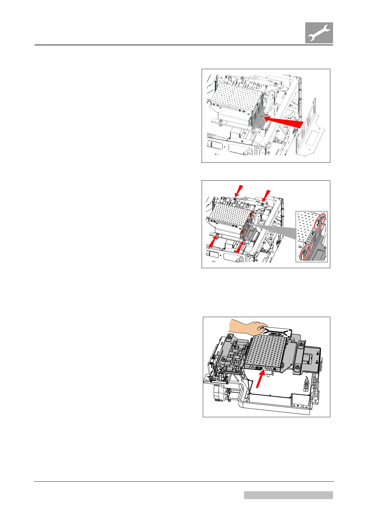
(3) Mount the PMT gauge on the light
collector.
Figure 16
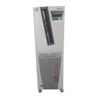
(4) Check the distance between PMT
gauge and PMI carrier (see two
circles in Figure 17):
The PMI carrier should just touch
the PMT ga
uge.
(5) If the distance is OK, continue
with step (9), otherwise continue
with next step.
(6) Open the four adjustment screws.
See arrows in Figure 17.
(7)
Adjust horizontal position as well
as the angle of the PMI board
carrier.
(8) Fasten the four adjustment
screws.
Figure 17
(9) Remove the PMI carrier.
(10) Remove PMT gauge.
(11) Mount PMT on the light collector.
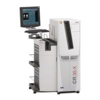
(12) Keeping the PMT in its mounting
position by hand, mount the PMI
board carrier. See Figure 18.
(13)
Re-assemble the digitizer.
(14) Perform a shading calibration.
Figure 18
Edition 1, Revision 3 CR 30-X Chapter 3.6 / 13
10-2009 Type 5175 / 100/110 Agfa Company Confidential