Chapter 4 205
Troubleshooting
Performance test failure troubleshooting
4. Troubleshooting
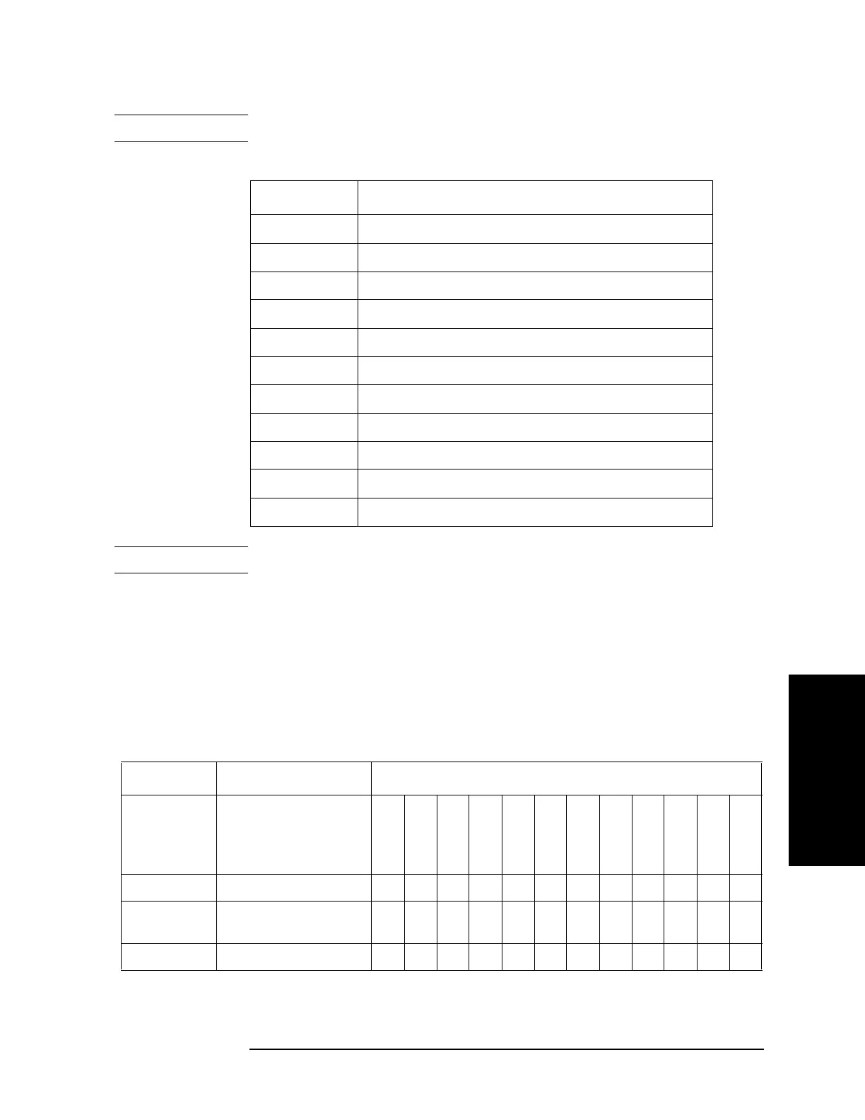
NOTE The meaning of abbreviations are shown in Table 4-8.
Table 4-8 The meaning of abbreviations
Abbreviation Meaning (Description)
OCXO OCXO Board
BAS Analog Base Module
SYN -SRC TESTED Synthesizer Module for Source
SYN -LCL TESTED Synthesizer Module for Local
VNR TESTED Level Vervier Module
RCV -1 TESTED Receiver Module Port 1
RCV -2 TESTED Receiver Module Port 2
RCV -3 TESTED Receiver Module Port 3
RCV -4 TESTED Receiver Module Port 4
T2 -SW T2 Switch
CBL Test Cable connection, Semi-Rgd Cable
NOTE Module configulation is shown Figure 4-13 for 2-port, and Figure 4-14 for 4-port.
Probable faulty board assembly or parts on Adjustment failure
Table 4-9 represents the relationships between the failed adjustment and probable faulty
assembly. If the adjustment failures in this troubleshooting, replace the assembly shown in
this table.
Note that this table lists some typical cases. There are possibilities that other assembly may
be faulty. To troubleshoot further, perform the diagnostics test procedures.
Table 4-9 Adjustment failure troubleshooting information
Probable faulty board assembly or parts
Failed
Adjustment
Failed test item
OCXO
BAS
SYN-SRC
SYN-LCL
VNR
RCV-1
RCV-2
RCV-3
RCV-4
DIS
T2-SW
CONN
OCXO
###
Frequency
Reference
## ###
AUX Input
###

 Loading...


