A20 User Manual (Revision 1.2) Copyright © 2013 Allwinner Technology Co., Ltd. All Rights Reserved. Page 118 / 812
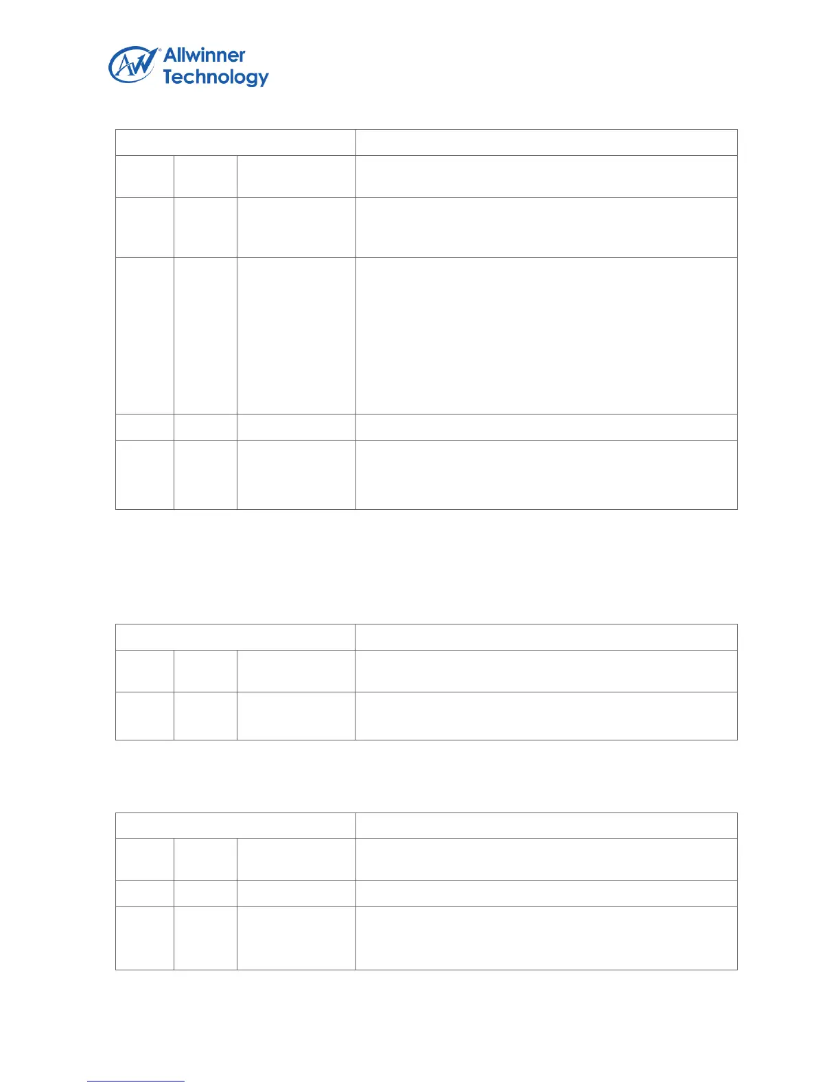
Register Name: TMR3_CTRL_REG
timer will not disable automatically.
1: Single mode. When interval value reached, the timer will
disable automatically.
TMR3_CLK_PRES.
Select the pre-scale of timer 3 clock source.
Timer 3 clock source is the LOSC.
00: /16
01: /32
10: /64
11: /
TMR3_EN.
Timer 3 Enable.
0: Disable, 1: Enable.
Note: the time between the timer disabled and enabled should be larger than 2*Tcycles(Tcycles=
Timer clock source/pre-scale).
1.9.3.13. TIMER 3 INTERVAL VALUE REGISTER
Register Name: TMR3_INTV_VALUE_REG
TMR3_INTV_VALUE.
Timer 3 Interval Value.
1.9.3.14. TIMER 4 CONTROL REGISTER(DEFAULT: 0X00000004)
Register Name: TMR4_CTRL_REG
TMR4_MODE.
Timer 4 mode.
0: Continuous mode. When interval value reached, the