Simplified Diagram of Single-Ended Reference
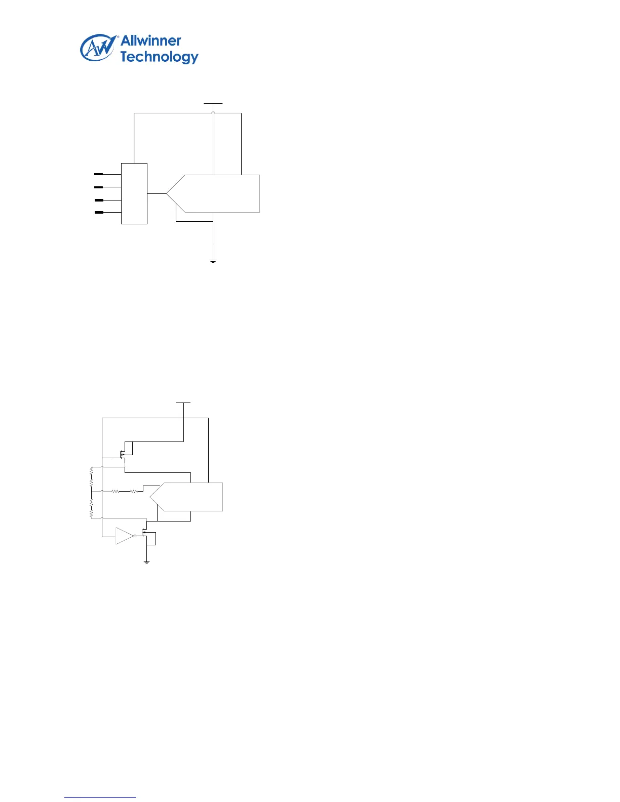
DIFFERENTIAL MODE
When the TP controller is in the measurement mode of X,Y,Z, the internal ADC is in differential mode.
The advantage of differential mode is that +REF and –REF can input directly to the Y+, Y-, which can
eliminate measurement error because of the switch on resistance. The disadvantage is that during
both the sample and conversion process, the driver will need to be on, which will increase the power
consumption.
Simplified Diagram of Differential Reference
SINGLE TOUCH DETECTION
The principle of operation is illustrated below, For an X coordinate measurement, the X+ pin is
internally switched to VCC_REF and X- to GND. The X plate becomes a potential divider, and the
voltage at the point of contact is proportional to its X co-ordinate. This voltage is measured on the Y+,
which carry no current (hence there is no voltage drop in R
Y
+ or R
Y
-). Due to the ratiometric
measurement method, the supply voltage does not affect measurement accuracy. The voltage
references VREF+ and VREF- are taken from after the matrix switches, so that any voltage drop in
these switches has no effect on the ADC measurement. Y coordinate measurements are similar to X