EasyManua.ls Logo

Allwinner A20 - Page 374

Allwinner A20
812 pages
Print Icon
To Next Page IconTo Next Page
To Previous Page IconTo Previous Page
Loading...
A20 User Manual (Revision 1.2) Copyright © 2013 Allwinner Technology Co., Ltd. All Rights Reserved. Page 374 / 812
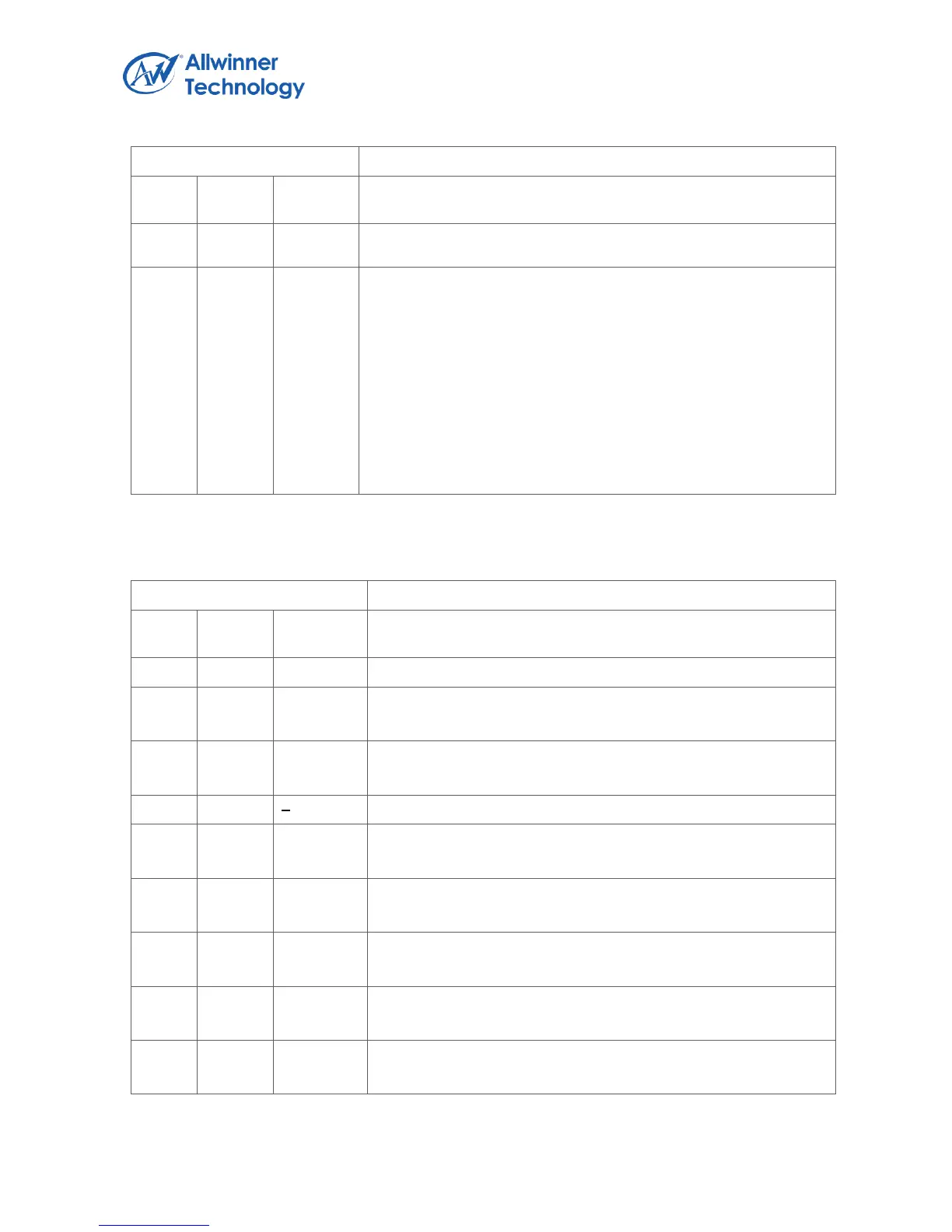
Offset Address: 0X0130
Register Name: CSI0_C1_INT_EN_REG
Bit
Read/W
rite
Default/
Hex
Description
capturing data is wrote to buffer as long as video capture
remains enabled.
00
R/W
0
CD_INT_EN
Capture done
Indicates the CSI has completed capturing the image data.
For still capture, the bit is set when one frame data has been
wrote to buffer.
For video capture, the bit is set when the last frame has been
wrote to buffer after video capture has been disabled.
For CCIR656 interface, if the output format is frame planar
YCbCr 420 mode, the frame end means the field2 end, the other
frame end means field end.
4.1.5.27. CSI CHANNEL_1 INTERRUPT STATUS REGISTER
Offset Address: 0X0134
Register Name: CSI0_C1_INT_STA_REG
Bit
Read/W
rite
Default/H
ex
Description
31:08
/
/
/
07
R/W
0
VS_PD
vsync flag
06
R/W
0
HB_OF_PD
Hblank FIFO overflow
05
R/W
0
PRTC_ERR_PD
04
R/W
0
FIFO2_OF_PD
FIFO 2 overflow
03
R/W
0
FIFO1_OF_PD
FIFO 1 overflow
02
R/W
0
FIFO0_OF_PD
FIFO 0 overflow
01
R/W
0
FD_PD
Frame done
00
R/W
0
CD_PD
Capture done

Table of Contents