EasyManua.ls Logo

Allwinner A20 - Page 572

Allwinner A20
812 pages
Print Icon
To Next Page IconTo Next Page
To Previous Page IconTo Previous Page
Loading...
A20 User Manual (Revision 1.2) Copyright © 2013 Allwinner Technology Co., Ltd. All Rights Reserved. Page 572 / 812
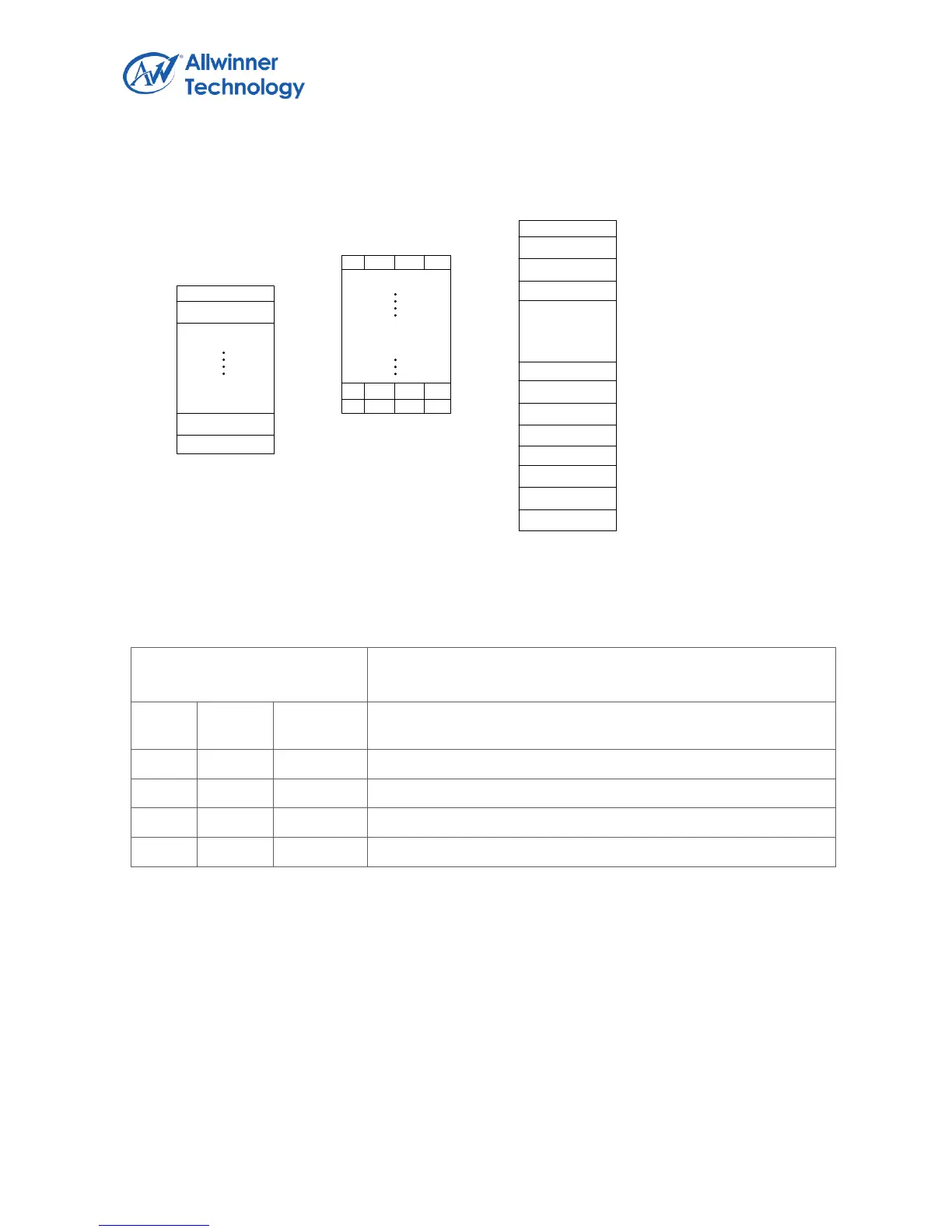
The following figure shows the RAM array used for internal frame buffer mode and the corresponding
colors output.
On chip SRAM array
Output color
On chip SRAM for internal
frame buffer
Internal frame buffer
Palette table
2bpp mode
3 2 0 2
1 3 2 2
3 3 0 1
bit7
bit0
2 R2 G2 B2
0 R0 G0 B0
2 R2 G2 B2
3 R3 G3 B3
1 R1 G1 B1
0 R0 G0 B0
3 R3 G3 B3
3 R3 G3 B3
2 R2 G2 B2
2 R2 G2 B2
3 R3 G3 B3
1 R1 G1 B1
Color1
Color0
Color254
Color255
0 R0 G0 B0
1 R1 G1 B1
254 R254 G254 B254
255 R255 G255 B255
5.4.4.55. GAMMA CORRECTION MODE
Offset:
0x4400-0x47FF
DE-on chip SRAM block
Bit
Read/W
rite
Default/H
ex
Description
31:24
R/W
UDF
Alpha channel intensity
23:16
R/W
UDF
Red channel intensity
15:8
R/W
UDF
Green channel intensity
7:0
R/W
UDF
Blue channel intensity
In gamma correction mode, the RAM array is used for gamma correction, each pixel’s alpha, red,
green, and blue color component is treated as an index into the SRAM array. The corresponding
alpha, red, green, or blue channel intensity value at that index is used in the actual color.
The following figure shows the RAM array used for gamma correction and the corresponding colors
output.

Table of Contents