A20 User Manual (Revision 1.2) Copyright © 2013 Allwinner Technology Co., Ltd. All Rights Reserved. Page 616 / 812
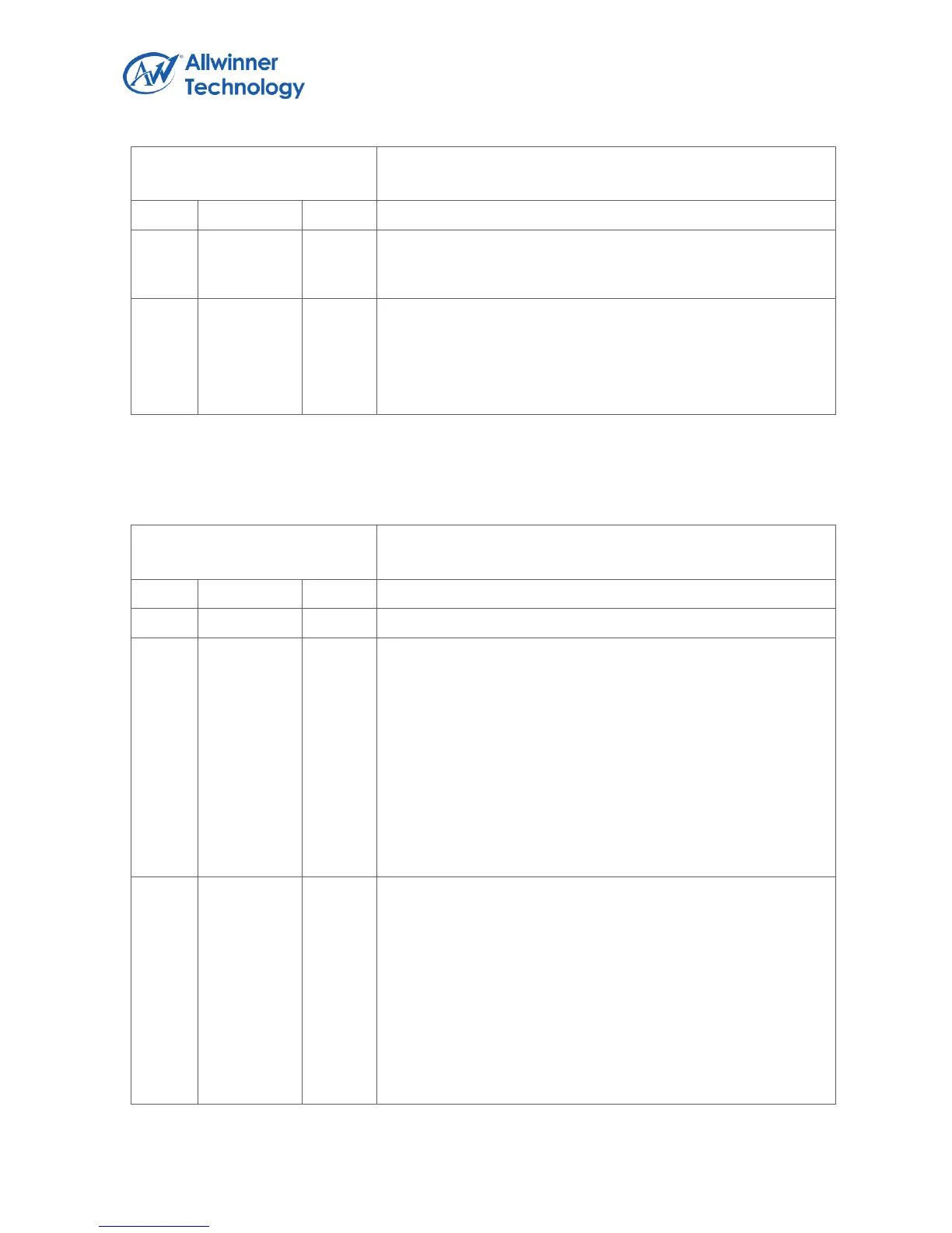
Register Name: UART_FCR
Default Value: 0x0000_0000
This resets the control portion of the receive FIFO and treats
the FIFO as empty. This also de-asserts the DMA RX request.
It is ‘self-clearing’. It is not necessary to clear this bit.
FIFOE
Enable FIFOs
This enables/disables the transmit (XMIT) and receive (RCVR)
FIFOs. Whenever the value of this bit is changed both the
XMIT and RCVR controller portion of FIFOs is reset.
6.4.4.8. UART LINE CONTROL REGISTER
Register Name: UART_LCR
Default Value: 0x0000_0000
DLAB
Divisor Latch Access Bit
It is writeable only when UART is not busy (USR[0] is zero)
and always readable. This bit is used to enable reading and
writing of the Divisor Latch register (DLL and DLH) to set the
baud rate of the UART. This bit must be cleared after initial
baud rate setup in order to access other registers.
0: Select RX Buffer Register (RBR) / TX Holding
Register(THR) and Interrupt Enable Register (IER)
1: Select Divisor Latch LS Register (DLL) and Divisor Latch
MS Register (DLM)
BC
Break Control Bit
This is used to cause a break condition to be transmitted to the
receiving device. If set to one the serial output is forced to the
spacing (logic 0) state. When not in Loopback Mode, as
determined by MCR[4], the sout line is forced low until the
Break bit is cleared. If SIR_MODE = Enabled and active
(MCR[6] set to one) the sir_out_n line is continuously pulsed.
When in Loopback Mode, the break condition is internally
looped back to the receiver and the sir_out_n line is forced
low.
 Loading...