A20 User Manual (Revision 1.2) Copyright © 2013 Allwinner Technology Co., Ltd. All Rights Reserved. Page 634 / 812
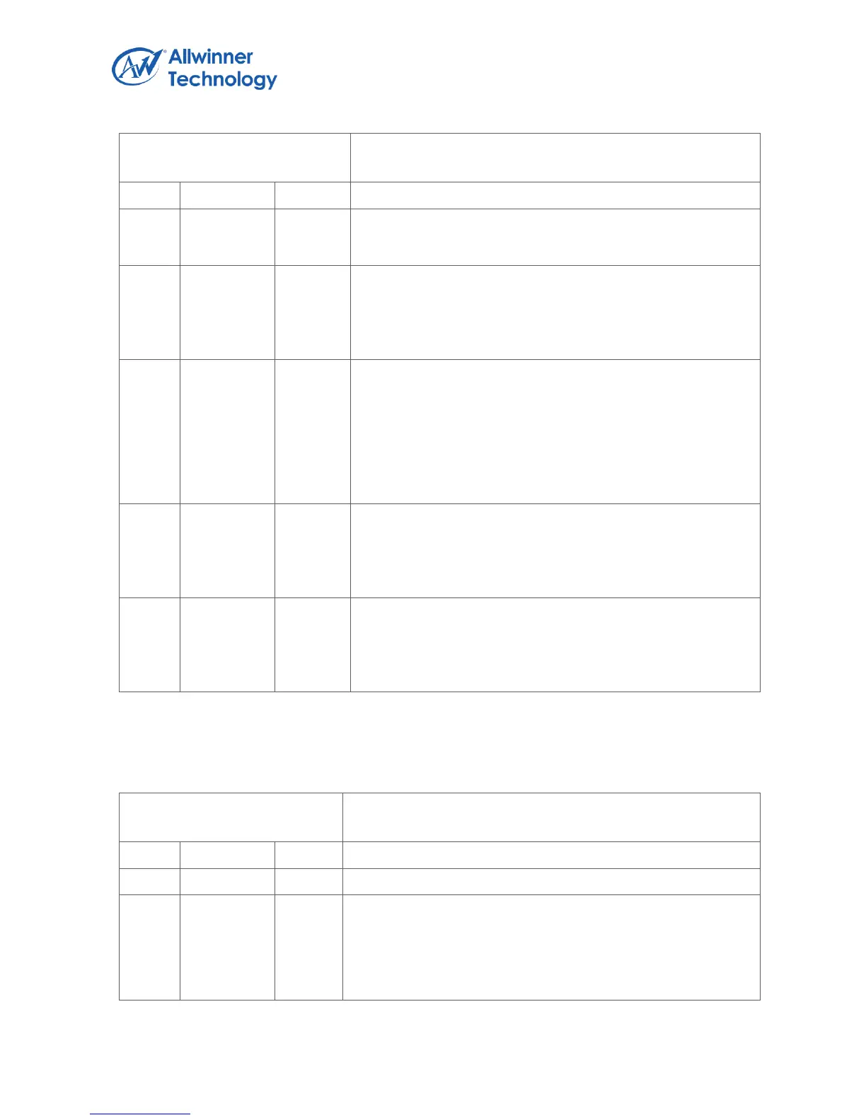
Register Name: PS2_GCTL
Default Value: 0x0000_0002
Note: This bit is just a status flag, it can not be cleared
directly, it can be cleared by clearing the status bits in FIFO
Status Register.
INT_EN
Interrupt Enable
0 – the interrupt signal is always low
1 – the interrupt signal will be high when INT_FLAG is set
SOFT_RST
Soft Reset
Setting this bit will reset transmitter and receiver of PS2
Module, and the status of transmitter and receiver will revert
to the default state, but not affect any control bits in register,
and data in TXFIFO/RXFIFO.
This bit will be cleared by hardware after reset is completed.
FUNC_SEL
Master/Device Function Select
1 – Master Function, connect to PS2 Keyboard or Mouse
0 – Device Function, connect to Computer
BUS_EN
PS2 Bus Enable
0 – Ignore PS2 Bus Input
1 – Response to PS2 Bus Input
6.5.5.2. PS2 DATA REGISTER
Register Name: PS2_DATA
Default Value: 0x0000_0000
PS2_DATA
When write, data will be write into TXFIFO, and will be transmit
on to the PS2 Bus.
When read, data is read out from RXFIFO, and it is received
from PS2 Bus.