A20 User Manual (Revision 1.2) Copyright © 2013 Allwinner Technology Co., Ltd. All Rights Reserved. Page 685 / 812
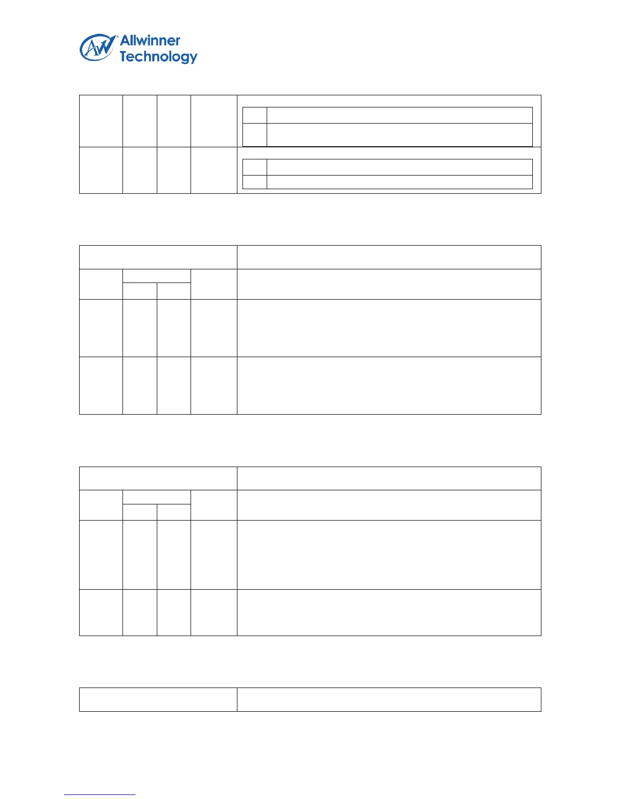
WritebackDoneHead Interrupt Disable
Disable interrupt generation due to Write back Done
Head;
SchedulingOverrun Interrupt Disable
Disable interrupt generation due to Scheduling Overrun;
Register Name: HcHCCA
Default Value:0x0
HCCA[31:8]
This is the base address of the Host Controller Communication
Area. This area is used to hold the control structures and the
Interrupt table that are accessed by both the Host Controller and
the Host Controller Driver.
HCCA[7:0]
The alignment restriction in HcHCCA register is evaluated by
examining the number of zeros in the lower order bits. The
minimum alignment is 256 bytes, therefore, bits 0 through 7 must
always return 0 when read.
6.8.7.8. HCPERIODCURRENTED REGISTER
Register Name: HcPeriodCurrentED(PCED)
Default Value: 0x0
PCED[31:4]
This is used by HC to point to the head of one of the Periodec list
which will be processed in the current Frame. The content of this
register is updated by HC after a periodic ED has been processed.
HCD may read the content in determining which ED is currently
being processed at the time of reading.
PCED[3:0]
Because the general TD length is 16 bytes, the memory structure
for the TD must be aligned to a 16-byte boundary. So the lower bits
in the PCED, through bit 0 to bit 3 must be zero in this field.
6.8.7.9. HCCONTROLHEADED REGISTER
Register Name: HcControlHeadED[CHED]
Default Value: 0x0