68
11 SELETRON CONNECTION
PLEASE CAREFULLY FOLLOW THE INSTRUCTIONS PROVIDED IN THIS CHAPTER. ANY MISTAKES
DURING SELETRON PAIRING/REPLACEMENT MAY LEAD TO SYSTEM OPERATION FAILURE.
BEFORE PROCEEDING, MAKE SURE YOU ARE ABLE TO HEAR THE ACOUSTIC SIGNALS COMING FROM THE MONITOR
LOCATED IN THE CABIN (DOORS OPEN, ETC.).
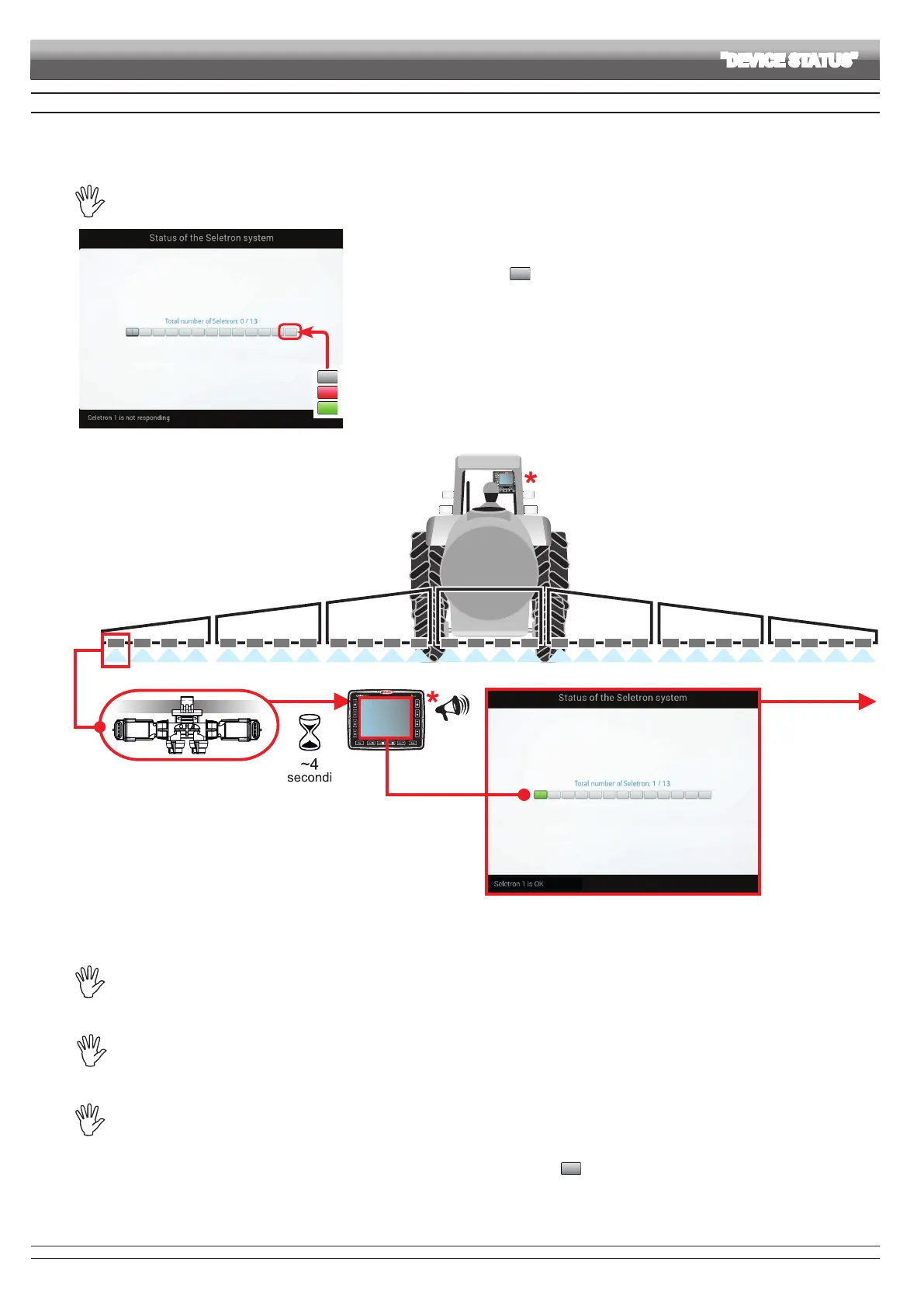
Seletron does not respond.
Power supply error on Seletron devices: power voltage lower than the allowed value.
Correct operation.
Fig. 230
• Access the menu Settings > Device status > Status of the Seletron system on Delta 80 (par. 10.8).
• Make sure that ALL SELETRON DEVICES ARE DISCONNECTED: they must be shown on the
display only with the symbols , as shown in Fig. 230.
Seletron 1 Seletron 2, 3, etc.
Fig. 231
• Connect the rst Seletron.
Seletron no. 1 is the rst on the left, when looking at the boom from behind (Fig. 231).
WAIT FOR THE ACOUSTIC SIGNAL BY Delta 80.
WAIT FOR Delta 80 TO DISPLAY THE GREEN SYMBOL FOR THE CONNECTED SELETRON (FIG. 231).
• ONLY NOW is it possible to proceed with the installation of the following Seletron.
WARNING: ALL SELETRON DEVICES MUST BE INSTALLED IN A SEQUENCE FROM LEFT TO RIGHT
(when looking at the boom from behind).
• Repeat the above steps, connecting all remaining Seletron devices from left to right until the end of the boom.
BEFORE CONNECTING A NEW SELETRON, MAKE SURE THAT THE PREVIOUS ONE HAS
BEEN PAIRED, that the acoustic signal has been made and that the relevant green symbol has been
displayed.
In case of errors during the pairing procedure, (the display shows the symbol ) reset all identication numbers and repeat the
procedure from the start (par. 10.1.14, Identification number reset).
ADVANCED SETUP "DEVICE STATUS"
CONTINUES > > >