Brake System
Argo Service Manual
Ontario Drive & Gear Limited www.odg.com
PH.(519)- 662-2840 FAX (519)- 662-2421
BR-39
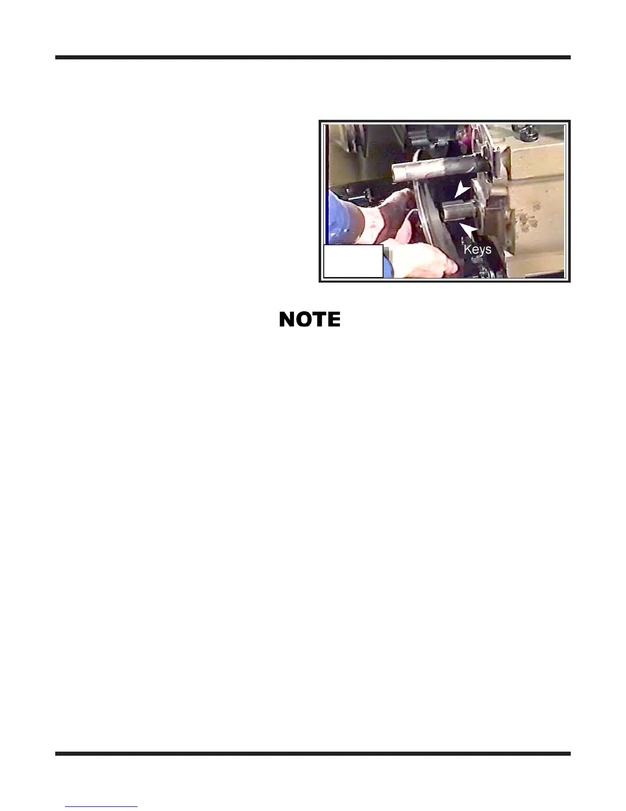
Installing the Brake Disc
i.. Apply an anti-seize compound to both
output shafts.
ii.. Place both keys in the keyways of the
output shafts.
iii. Align the keys with the keyways on the
brake disc and slide the disc on to the
shaft. The sprocket on the brake disc
should be facing outward.
Photo BR-68
Vehicles equipped with the brake cooling system will require the cooling duct to be moved
out of the way far enough to allow the brake disc on. Seat the brake disc firmly against
the shoulder of the output shaft.
iv. Re-position the cooling duct and and secure with the two 1/4"-20x1" phillip head
screws (CONQUEST MODELS) or retightening the gear clamp on the overhead
mounting bracket ( BIGFOOT & RESPONSE MODELS)
BR-68
On vehicles produced prior to S/N CB16459, RB16446, BF11143, S11188 &
SN11196
IMPORTANT
On vehicles produced from S/N CB16459, RB16446, BF11143, S11188 &
SN11196 :
A small number of vehicles used a shim washer in behind the brake disc. This shim
washer will need to be reinstalled to the output shaft before the brake disc is slipped
on. This is required to align the brake disc to the hydraulic caliper properly. Take
note of the transmission serial number to correctly identify these vehicles.
All 6 wheel hydraulic brake vehicles with serial numbers between BF11321 & BF11390.
i Apply anti-seize compound to the spline of the output shafts.
All 8 wheel vehicles with serial numbers between RB16700 & CB16778.
v. Apply blue LOCTITE 242 to the threads of the brake disc mounting bolt and install
it along with the lockwasher, clamping washer and any other spacers or washers that
were used previously. See NOTES on page BR-37.