Wheels, Axles & Chains Argo Service Manual
Ontario Drive & Gear Limited www.odg.com
PH.(519)- 662-2840 FAX (519)- 662-2421
WA-36
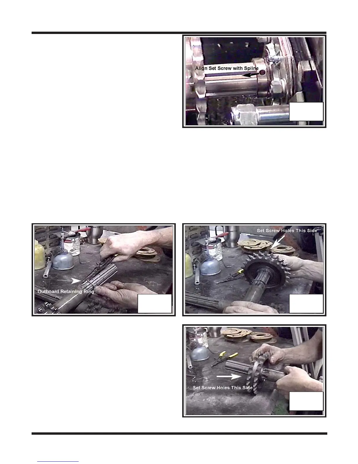
x. Align the 2 set screw holes of the inner
bearing, with the lower part of the spline
on the idler shaft. Apply blue 242
LOCTITE to the holes, as well as the
threads of the set screws, and install.
Torque to specifications.
Photo WA-77
WA-77
On vehicles manufactured from S/N
CB16970, RB17033, BF11543 &
V6016200000C12747:
Left Hand Side Idler Axle
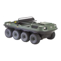
i. Slip the “outboard” retaining ring on to the idler shaft past both machined grooves
(vehicles manufactured from 2007 will have (4) machined grooves on this idler
shaft), and to the end of the spline. Photo WA-78
ii. Next, install the floating sprocket with the set screw hole facing inwards (towards
the inner bearing side). Place it up against the retaining ring. Photo WA-79
WA-78 WA-79
Right Hand Side Idler Axle
iii. Install the floating sprocket with the set
screw hole facing inwards (towards the
inner bearing side). Slip it on as far as it
will go. Photo WA-80
WA-80
iv. Install the “inboard” retaining ring up
against the sprocket. Photo WA-81