Argo Service Manual Clutch System
Ontario Drive & Gear Limited www.odg.com
PH.(519)- 662-2840 FAX (519)- 662-2421
CS-23
CS-53
CS-54
Driven Clutch Reassembly (126-24 & 127-129)
1. Press the oilite bushing into the movable face and secure with the roll pin or retain-
ing ring. A new bushing requires re-drilling the hole in the movable face (126-24
driven clutches only),once the bushing is in position.
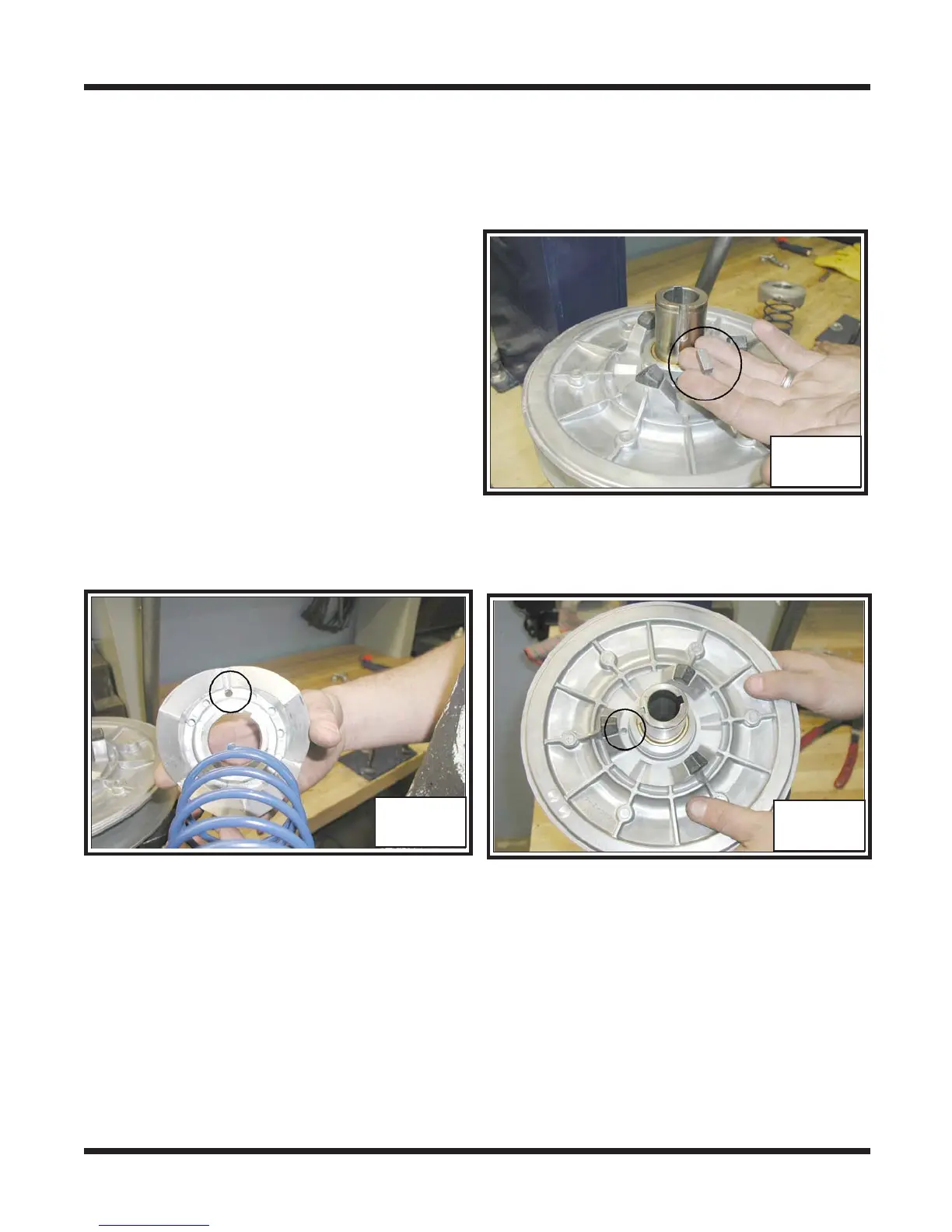
2. Slip the movable face back on to the
fixed pulley after installing all spacers
and snap ring to the fixed face shaft.
Slide the small key into the key way of
the fixed shaft. Photo CS-52
CS-52
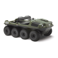
3. There are 6 spring tension adjustment
holes in the cam that are numbered 1
through 6. Insert the one end of the cam
spring into the number 3 hole. Photo
CS-53
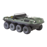
4. There is 1 hole within the movable face pulley. Insert the other end of the cam
spring into this hole. Photo CS-54
Driven Clutch Reassembly (Avenger 127-136)
i. Slip the movable face back on to the fixed pulley after installing all spacers and snap
ring to the fixed face shaft. Slide the small key into the key way of the fixed shaft.
ii. Locate the # 10 marking on the moveable face. The cam spring will be inserted into
the hole across from this number. Photo 53A
iii. Insert the other end of the clutch spring into th e # 2 hole of the cam. Photo 54A