Wheels, Axles & Chains Argo Service Manual
Ontario Drive & Gear Limited www.odg.com
PH.(519)- 662-2840 FAX (519)- 662-2421
WA-40
On vehicles manufactured from S10178 & SN10191 both inner and outer flanges are
greasable. Earlier models only utilize the greasable flange at the inner bearing.
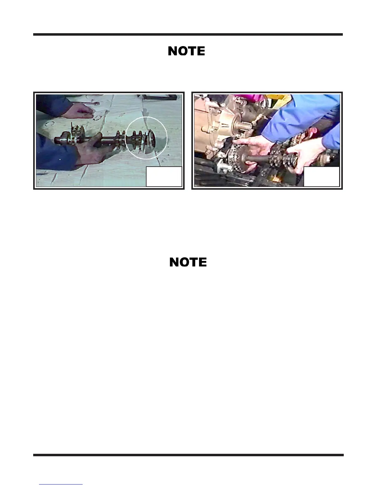
6. Install the idler shaft assembly into the vehicle. Slip the inner bearing end of the
shaft in first, then drop the outer bearing end, connecting bearing and flanges to the
studs. Photo WA-93
WA-92 WA-93
7. Install all mounting hardware to the flanges and tighten securely. Torque to specifi-
cations.
On vehicles manufactured prior to S/N S10178 & SN10191, slide an open end wrench
between the lower body and frame at the outer idler axle bearing flange assembly. Hold
the head of the bolt while tightening the mounting hardware.
8. Install the brake disc. Depending on the year of vehicle, the output shafts and brake
discs may either be keyed or splined (See NOTE at bottom of page BR-38). Apply
blue 242 LOCTITE to the threads of the mounting bolt and secure with lockwasher
and flat washer. The brake disc bolt will be easier to torque later once the calipers
have been installed and applied to hold it secure.
IMPORTANT
Apply anti-seize to output shafts before installing the brake discs.
Aligning the Idler Shaft (Vanguard & Vanguard2 Models)
9. Idler shafts must be aligned with the brake disc sprocket using a square and V
Block.