CHAPTER 4 REFERENCE GUIDE
Page 4-49
091-00019-001 REV B
EFD1000 C3 Pro PFD Pilot’s Guide
When a GPS source’s position data are invalid or no longer available, an amber
annunciation, GPS1, GPS2, or RSM GPS, is shown in the lower left corner of the
Navigation Display to indicate which has failed (Figure 4-99).
4.4.13. Ground Track Marker
When congured with a GPS that provides ground track data, a Ground Track Marker is
displayed on the compass scale to indicate the aircraft’s ground track. This marker may be
used to compensate for wind drift during ight (Figures 4-100 and 4-101). The Ground
Track Marker is removed from the display when ground track data is not available or invalid.
4.4.14. GPS OBS Operation with a PFD and a Mechanical
Standby Nav Indicator
When the PFD and a mechanical standby Nav indicator are both connected to an integrated
VOR/Localizer/GPS Navigation system, the standby indicator and the PFD operate normally in
all VOR, GPS and localizer modes.
When the GPS OBS mode is selected, the PFD Selected Course (CRS) control commands the
GPS OBS course and the mechanical standby nav indicator’s OBS course selector is ignored
by the integrated navigation system. Deviation indications are shown on both displays.
When the PFD is turned o, the course selector on the mechanical standby Nav indicator
commands the GPS OBS value.
4.4.15. Course Pointer Operation with Integrated VOR/
Localizer/GPS Navigation Systems
During manual or automatic operation of the integrated system, when transitioning from
GPS guidance to VOR or localizer guidance, the course pointer on the should manually be set
to the appropriate course.
Figure 4-99
Invalid or Failed GPS Annunciations
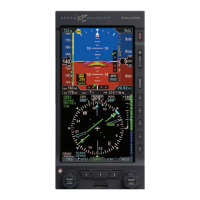
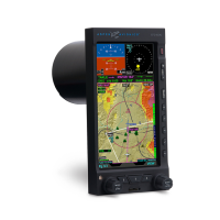
Figure 4-100
ARC Compass Mode, Ground Track Marker
Figure 4-101
360° Compass Mode, Ground Track Marker