CHAPTER 2 CONTROLS AND DISPLAY
Page 2-32
091-00019-001 REV B
Page 2-33
091-00019-001 REV BEFD1000 C3 Pro PFD Pilot’s Guide
2.3.4.1. Direction Indicator (Magnetic Compass)
The center of the Navigation Display is the Direction Indicator, or Magnetic Compass.
The compass always shows the current magnetic heading of the aircraft, both with a
numerical value of the current heading at the top of the display, and with a lubber line,
or pointer, to that heading on either a full or partial compass rose. This slaved compass
system compensates both for the turning and acceleration errors exhibited by wet
compasses and for precession errors found in common Directional Gyros. The pilot does
not need to make adjustments to the heading indicator during the ight.
The Direction Indicator includes capabilities to make it an electronic Horizontal
Situation Indicator (HSI) with dual Bearing Pointers. The HSI features are explained in a
separate section below.
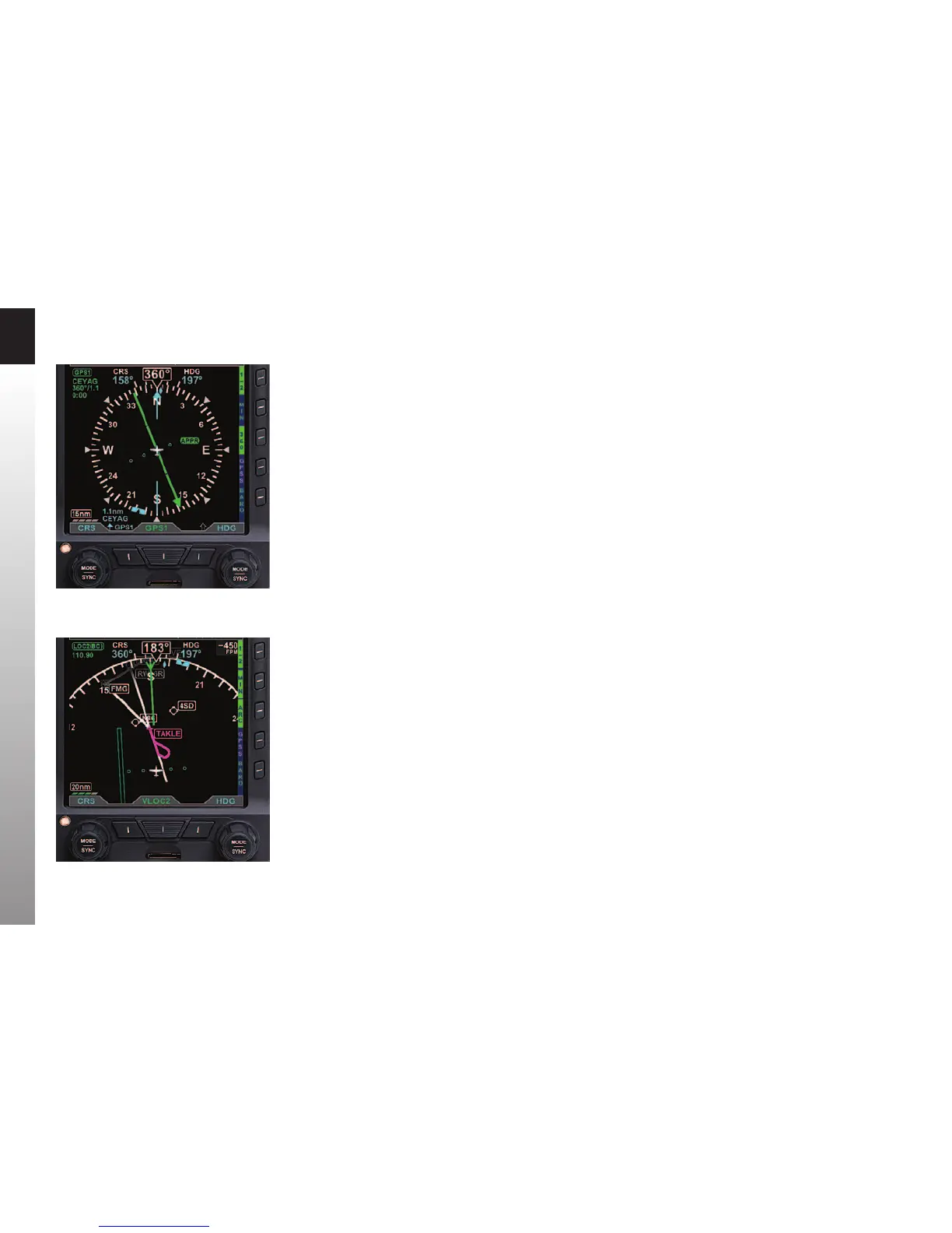
Compass Modes: 360º vs. ARC
The Direction Indicator can be presented in either a full 360º Compass rose mode
(shown in Figure 2-36), or in a 100º ARC mode (Figure 2-37).
The 360° Compass Mode resembles the mechanical instrument, with the ownship
position in the center of the display.
The ARC Compass Mode provides an extended forward view with the ownship position
at the bottom of the display. The ARC Compass is especially good for displaying ight
plan and basemap details.
The 360/ARC Hot Key is used to toggle the display between 360° and ARC Compass
Modes, with the current mode shown in green adjacent to the Hot Key.
Figure 2-36
360° Compass Mode
Figure 2-37
ARC CDI Compass
Mode with Basemap