CHAPTER 2 CONTROLS AND DISPLAY
Page 2-36
091-00019-001 REV B
Page 2-37
091-00019-001 REV B EFD1000 C3 Pro PFD Pilot’s Guide
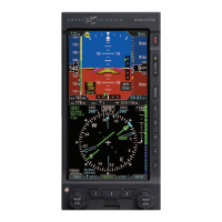
Figure 2-46
Rate of Turn Indicator, Rate Shown >6º/second
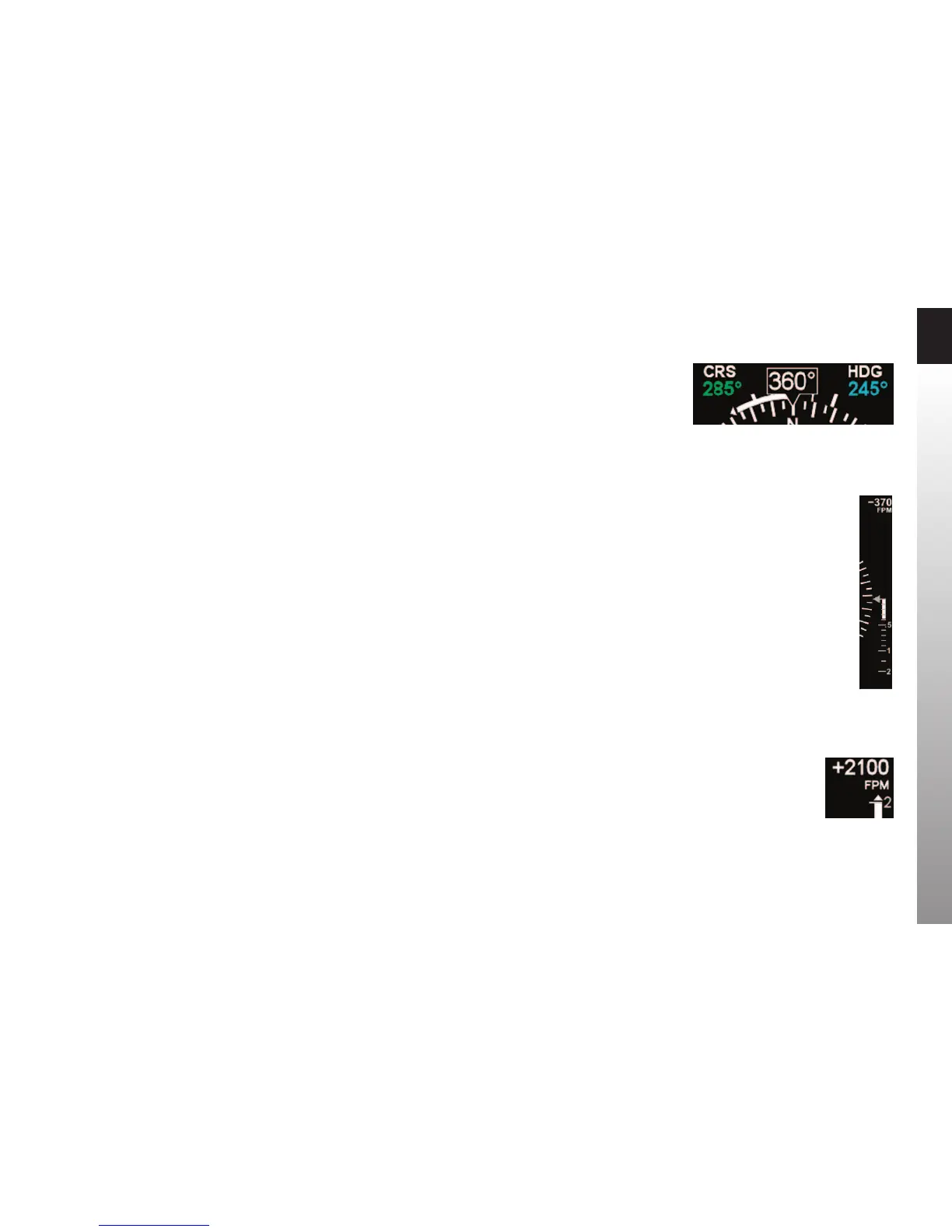
Figure 2-47
VSI Tape Showing 370 FPM Descent
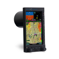
Figure 2-48
VSI Tape Capped, Digital Value
Showing 2,100 FPM Climb
2.3.4.7. Rate of Turn Indicator
A Rate of Turn Indicator (Figure 2-2, No. 48) with a range of 0 to 6 degrees per second
is provided for both the 360 and ARC Compass Modes. The indicator consists of a
curved white tape that extends from the Magnetic Heading’s lubber line and in the
direction of the turn, along the outer curve of the compass card.
The Rate of Turn Indicator features an outer thick white tick mark for a Standard Rate
turn, and an inner thin white tick mark for Half-Standard Rate turns. A Standard Rate,
two-minute turn equals 3 degrees per second. When the rate of turn exceeds 6 degrees
per second, an arrowhead is added to the end of the tape to show that the rate of turn
has exceeded the limits of the indicator (Figure 2-46).
2.3.4.8. Vertical Speed Indicator (VSI)
Whenever the vertical speed exceeds +/- 100 feet per minute (FPM), the vertical
speed is indicated by a rising/sinking white vertical tape and associated scale markers
immediately to the right of the compass rose (Figure 2-2, No. 57 and Figure2-47).
A numerical value of the aircraft’s vertical speed is shown directly above the tape, in the
upper right-hand corner of the Navigation Display (Figure 2-2, No. 56). Rates of up to
±2,000 FPM are indicated by the tape, while the numerical value will display rates of
up to ±9,990 FPM. A white triangle caps the tape whenever rates exceed ±2,000 FPM
(Figure 2-48). The vertical speed numerical value will be dashed whenever the vertical
speed exceeds +/- 10,000 FPM. In the ARC Compass Mode, only the numerical vertical
speed value is presented.