CHAPTER 2 CONTROLS AND DISPLAY
Page 2-30
091-00019-001 REV B
Page 2-31
091-00019-001 REV BEFD1000 C3 Pro PFD Pilot’s Guide
NOTE
The Vertical Deviation Indicator (VDI) and Lateral
Deviation Indicator (LDI) are part of the navigation
instruments and are displayed on the Attitude Display
during instrument approaches.
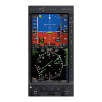
2.3.4. Navigation Display
The lower half of the PFD is the Navigation Display (Table 2-9 and Figure 2-35), which
shows a wide range of navigation information and ight data, including:
• Horizontal Situation Indicator (HSI), with Course Pointer and Deviation
Indicator (CDI), and Heading Bug.
• 360° and ARC Compass rose display modes.
• Numeric displays of current magnetic heading, selected heading (HDG), and
selected course (CRS).
• Information about the selected CDI navigation source, or active GPS waypoint.
• Ground Track Marker.
• Vertical Speed Indicator (VSI) tape and numerical rate value.
• Rate of Turn Indicator.
• Dual bearing pointers (RMI) (360° Compass mode only).
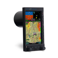
• Situational Awareness Map display.
• Course Deviation Indicators (CDI) and Bearing Pointers, navigation source
information.
• GPS annunciations (TERM, APPR, WPT, and MSG).
• Caution annunciations for abnormal GPS status.
When connected to a GPS navigator, basic mapping can also be displayed under
the HSI, including GPS ight plan legs and waypoints, (and when connected to a
compatible GPS) Basemap data (airports, VORs, NDBs, and intersections).