CHAPTER 2 CONTROLS AND DISPLAY
Page 2-36
091-00019-001 REV B
Page 2-37
091-00019-001 REV BEFD1000 C3 Pro PFD Pilot’s Guide
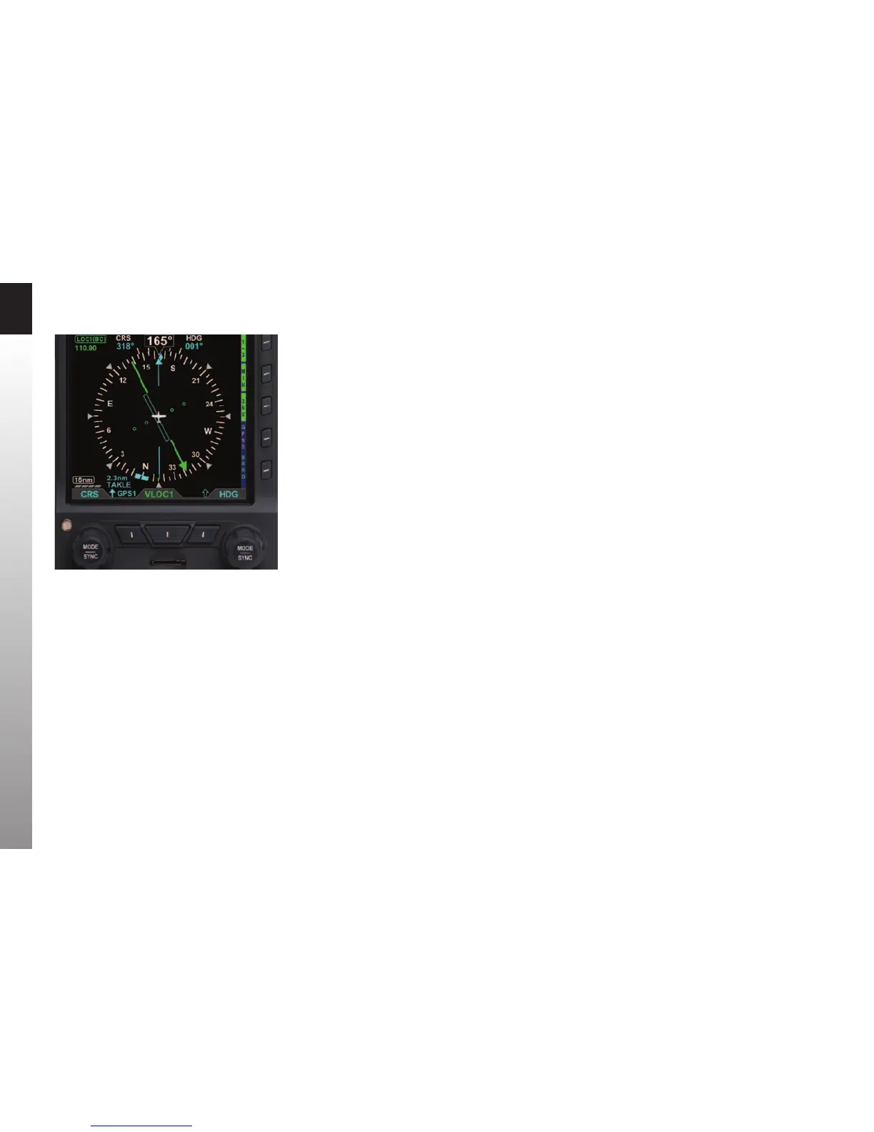
2.3.4.6. Bearing Pointers
The Single- (Figure 2-2, No. 58) or Double-line (Figure 2-2, No. 61) Bearing Pointers
can be overlaid on the HSI (Figure 2-45). Use the Lower Left and the Lower Right
Source Select Buttons (Figure 2-2, No. 12 and No. 10) to select the nav sources for the
Bearing Pointers, or select none (blank) to remove a Bearing Pointer from the display.
Bearing Pointers always point to a VOR or waypoint. When coupled to a VOR source,
the tail of the Bearing Pointer indicates the VOR radial on which the aircraft is currently
located. Bearing Pointers are excellent tools for identifying crossing radials, ying DME
arcs, and improving situational awareness.
Bearing Pointers are only available in the 360° Compass Mode. Any available navigation
source may be coupled to either Bearing Pointer. If coupled to a source that does not
provide angular bearing data, such as a localizer, the Bearing Pointer is not shown, and
the source is slashed as invalid.
Each Bearing Pointer has an associated Source Information Block that displays
information about the source of the Bearing Pointer data. This may include distance
to station (if coupled to a GPS waypoint) and either the station identier or the tuned
frequency for a VOR. This information is only presented when it is reported to the PFD
by the connected equipment.
Figure 2-45
BRG#1 Set to GPS1 TAKLE (Single Line Bearing Pointer)