CHAPTER 2 CONTROLS AND DISPLAY
Page 2-28
091-00019-001 REV B
Page 2-29
091-00019-001 REV BEFD1000 C3 Pro PFD Pilot’s Guide
Figure 2-32
Instrument Approach
Indications
Figure 2-33
Decision Height
Annunciation
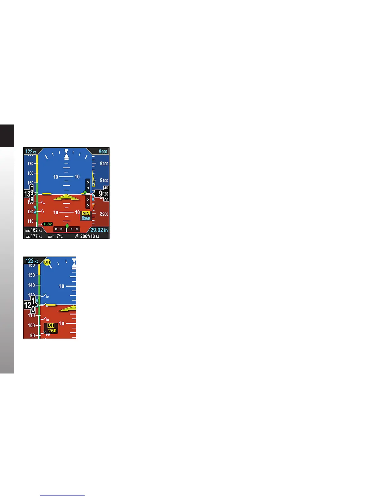
2.3.2.4. Instrument Approach Indicators
Additional indicators are shown on the Attitude Display when ying certain types of
instrument approaches. These enable the pilot to maintain a tighter instrument scan on
the ADI, reducing workload and improving safety (Figure 2-32).
A Lateral Deviation Indicator (LDI) (Figure 2-2, No. 37) is presented on the attitude
indicator whenever the pilot has selected an ILS, LOC, LOC Back Course (BC), or a GPS
approach and valid lateral course guidance is being received. The LDI’s navigation source
is annunciated to the left of the LDI (Figure 2-2, No. 31). A Vertical Deviation Indicator
(VDI) (Figure 2-2, No. 34)) is presented on the attitude indicator whenever the LDI is
shown and valid glide slope signal is being received, such as from an ILS or WAAS GPS LPV.
Whenever the lateral or vertical deviation exceeds the maximum displayable range of
LDI or VDI scale (2.5 dots), the deviation diamond turns into a hollow, ghosted image
pegged to the corresponding side. As soon as the deviation diamond comes into range,
the diamond turns solid green, making it easy to identify when the needle is “alive”.
Additionally, the pilot can pre-set the instrument approach minimums (MIN) with
the MIN Hot Key. Once the MIN data eld value is set to a Decision Altitude, Decision
Height, or Minimum Descent Altitude, the PFD provides a MINIMUMS annunciation
when the aircraft reaches or descends below this altitude (Figure 2-2, No. 28).
Additionally there are three minimums markers shown on the altitude tape — a green
marker 500 feet above minimums; a hollow yellow triangle in the area from 100 feet to
200 feet above minimums; and a red and yellow marker at the programmed Selected
Minimums value (see Section 4.2.3.4. MINIMUMS Annunciation for more details).
If a Radar Altimeter is installed in the aircraft and connected to the PFD, a Decision
Height annunciation (Figure 2-2, No. 27 and No. 29) will be displayed when the
aircraft descends to, or below, the selected radar altitude (Figure 2-33).