CHAPTER 2 CONTROLS AND DISPLAY
Page 2-32
091-00019-001 REV B
Page 2-33
091-00019-001 REV B EFD1000 C3 Pro PFD Pilot’s Guide
Navigation Information
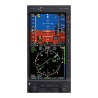
Regardless of Compass Mode setting, the current magnetic heading is always shown
at the top center of the Navigation Display (Figure 2-2, No. 50 and Figure 2-38). The
HDG Bug setting is shown in the Selected Heading Field (Figure 2-2, No. 52). This eld
is always visible even if the HDG Bug itself is only partially visible in ARC Compass Mode.
Similarly, on the HSI, the current Course setting (CRS) (Figure 2-2, No. 51) is always
shown, whether or not the Course Pointer itself is visible in ARC Compass Mode.
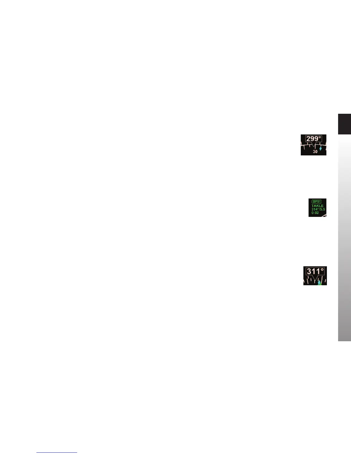
A Navigation Source Information Block (Figure 2-2, No. 65 and Figure 2-39) is
presented in the upper left corner of the Navigation Display. The Source Information
Block indicates the selected navigation source (coupled to the CDI on the PFD HSI),
and its associated mode (e.g., GPS, VOR, ILS, LOC) . Information is provided about
the selected source, including, when available, the waypoint or navaid identier or
frequency, bearing and distance, and the estimated time to the active waypoint.
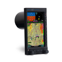
Ground Track Marker
When the PFD is connected to a compatible GPS, a blue Ground Track Marker is
displayed on the compass rose at the value that corresponds to the aircraft’s ground
track (Figure 2-2, No. 49 and Figure 2-40).
When the Ground Track Marker is aligned with the Course Pointer on the PFD HSI, the
aircraft is tracking on, or parallel to its desired track.
To align the Ground Track Marker with the Course Pointer, turn away from the direction
in which the diamond is oset from the Course Pointer (think of it as a turn to pull the
Ground Track Marker toward the Course Pointer).
Figure 2-38
Magnetic Heading
Figure 2-39
Navigation Source
Information Block
Figure 2-40
Ground Track Marker