Page viii
091-00019-001 REV B
Page ix
091-00019-001 REV B EFD1000 C3 Pro PFD Pilot’s Guide
Table of Figures
Figure 1 C3 Pro PFD Display, Knobs, Buttons, and Keys .....................xxviii
Chapter 1
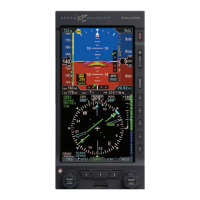
Figure 1-1 EFD1000 C3 Pro Display Unit .......................................................... 1-1
Figure 1-2 Single Display EFD1000 PFD System .........................................1-2
Figure 1-3 Dual Display System: PFD & MFD ................................................. 1-2
Figure 1-4 Trio Display System: PFD & Dual MFDs .....................................1-3
Figure 1-5 EFD 1000 C3 Pro PFD System Architecture............................1-4
Figure 1-6 EFD1000 Display Unit Rear Connections ................................1-5
Figure 1-7 Conguration Module (CM) ............................................................1-6
Figure 1-8 Analog Converter Unit (ACU) ........................................................ 1-6
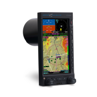
Figure 1-9 Remote Sensor Module (RSM) ....................................................... 1-7
Chapter 2
Figure 2-1 EFD1000 C3 Pro PFD ............................................................................ 2-2
Figure 2-2 EFD1000 C3 Pro PFD Display Elements .................................... 2-3
Figure 2-3 Left and Right Knobs and Corresponding Fields ...............2-6
Figure 2-5 Editing the HDG eld...........................................................................2-8
Figure 2-6 HDG eld updated and inactive ................................................... 2-8
Figure 2-7 CDI and Bearing Pointer Source Select Buttons .................2-9
Figure 2-8 Hot Key Menu Legend .....................................................................2-12
Figure 2-9 Hot Key Menu 2 of 2 ......................................................................... 2-13
Figure 2-15 Menu Navigation Mode ...............................................................2-14
Figure 2-16 Menu Edit Mode ...............................................................................2-15
Figure 2-17 Menu ........................................................................................................2-15
Figure 2-18 Menu Text - Editable ..................................................................... 2-16
Figure 2-19 Menu Text - Enabled for Editing..............................................2-16
Figure 2-20 Menu Text - Status Only ..............................................................2-16
Figure 2-21 Menu Text - Disabled ....................................................................2-16
Figure 2-22 Menu Display ......................................................................................2-16
Figure 2-23 EDIT VALUE Displays Above Right Knob ............................ 2-17
Figure 2-24 Display Brightness in BRT AUTO Mode ...............................2-18
Figure 2-25 Display Brightness in BRT ADJUST Mode ..........................2-18
Figure 2-26 EFD1000 C3 Pro PFD Display Areas .....................................2-20
Figure 2-27 Attitude Display Components .................................................2-23
Figure 2-28 Slip/Skid ................................................................................................. 2-24
Figure 2-29 Flight Director ....................................................................................2-24
Figure 2-30 Airspeed Tape ..................................................................................... 2-25
Figure 2-30a Mach Number Display ................................................................2-26
Figure 2-31 Altitude Tape .......................................................................................2-27
Figure 2-33 Decision Height Annunciation ................................................ 2-28
Figure 2-32 Instrument Approach Indications .........................................2-28
Figure 2-34 Data Bar Components ...................................................................2-29
Figure 2-35 Navigation Display Components ........................................... 2-31