Installation & Maintenance Manual Contents
Version 6.8 7 Microsoft Lync Server
List of Figures
Figure 1-1: SBA Home Page (Additional AudioCodes Applications Link) New SBA Image ..................16
Figure 1-2: SBA Home Page (Additional AudioCodes Applications Link) SBA Upgrade ......................16
Figure 1-3: Typical Branch Office Deployments .....................................................................................17
Figure 1-4: Summary of Steps for Installing and Configuring SBA ........................................................18
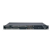
Figure 3-1: Mediant 1000B SBA Front Panel .........................................................................................23
Figure 4-1: Rear Panel of Mediant 1000B SBC and Gateway ...............................................................25
Figure 5-1: OSN3B and OSN4 Module Ports .........................................................................................28
Figure 5-2: OSN3B and OSN4 Module LEDs ........................................................................................29
Figure 5-3: OSN3 Module Ports .............................................................................................................32
Figure 5-4: OSN3 Module LEDs .............................................................................................................33
Figure 5-5: RJ-45-to-DB-9 Serial Cable Adapter....................................................................................35
Figure 5-6: HDMX Module ......................................................................................................................36
Figure 6-1: Grounding the Device ..........................................................................................................39
Figure 6-2: LAN Port-Pair Groups and Web Interface String Names ....................................................41
Figure 6-3: RJ-45 Connector Pinouts for LAN........................................................................................41
Figure 6-4: Connecting to LAN ...............................................................................................................42
Figure 6-5: RJ-11 Connector Pinouts for FXS........................................................................................43
Figure 6-6: RJ-45 Connector Pinouts for BRI.........................................................................................44
Figure 6-7: Cabling (Ports 1 and 2) PSTN Fallback ...............................................................................45
Figure 6-8: RJ-48c Connector Pinouts for E1/T1 ...................................................................................46
Figure 6-9: Cabling (Ports 1 and 2) PSTN Fallback ...............................................................................47
Figure 7-1: Connecting Mediant 1000B SBA LAN Port on CRMX Module (Front Panel) ......................49
Figure 7-2: Login Screen ........................................................................................................................49
Figure 7-3: IP Settings Screen ...............................................................................................................50
Figure 7-4: Maintenance Actions: Reset Gateway .................................................................................50
Figure 7-5: Physical Ports Settings Page ...............................................................................................51
Figure 8-1: New Object – Computer Dialog Box ....................................................................................55
Figure 8-2: RTCUniversalReadOnlyAdmins ...........................................................................................56
Figure 9-1: Menu Path to Topology Builder Program Lync 2013 ...........................................................58
Figure 9-2: Menu Path to Topology Builder Program Lync 2010 ...........................................................59
Figure 9-3: Topology Builder Lync 2013 ................................................................................................59
Figure 9-4: Topology Builder Lync 2010 ................................................................................................60
Figure 9-5: Lync Server 2013 Topology Builder .....................................................................................60
Figure 9-6: Lync Server 2010 Topology Builder .....................................................................................61
Figure 9-7: Identify the Site ....................................................................................................................61
Figure 9-8: Specify Site Details ..............................................................................................................62
Figure 9-9: New Branch Site Successfully Defined ................................................................................63
Figure 9-10: Define the Survivable Branch Appliance FQDN ................................................................63
Figure 9-11: Select the Front End Pool ..................................................................................................64
Figure 9-12: Select an Edge Server .......................................................................................................64
Figure 9-13: Define the PSTN Gateway-Lync 2013 ...............................................................................65
Figure 9-14: Define the PSTN Gateway-Lync 2010 ..............................................................................65
Figure 9-15: Publish Topology Selection ................................................................................................67
Figure 9-16: Publish the Topology .........................................................................................................67
Figure 9-17: Publish Wizard Complete ...................................................................................................68
Figure 10-1: Connecting Mediant 1000B SBA LAN Port on CRMX Module (Front Panel) ....................72
Figure 10-2: HDMI Connection ...............................................................................................................73
Figure 10-3: Cabling OSN3B and OSN4 to PC for Serial Communication ............................................73
Figure 10-4: Cabling OSN3 to PC for Serial Communication ................................................................74
Figure 10-5: Welcome to SBA Screen ...................................................................................................75
Figure 10-6: SBA Home Screen .............................................................................................................75
Figure 10-7: Connecting to LAN Port on OSN3B/OSN4 Module (Rear Panel View) .............................76
Figure 10-8: Connecting to LAN Port on OSN3 Module (Rear Panel View) ..........................................76
Figure 10-9: Welcome to SBA Screen ...................................................................................................77
Figure 10-10: SBA Home Screen ...........................................................................................................77
 Loading...