CHA NGE PARA METERS 107
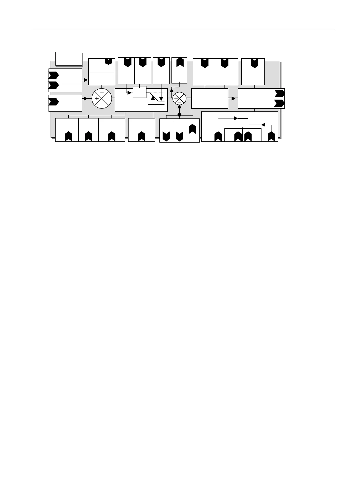
6.9.1 FIELD CONTROL / Block diagram
1) Voltage output clamp. This is an open loop setting of the field bridge-firing angle allo wing the DC
output voltage to be set bet w een 0 to 90% of the incoming supply voltage. E. g. for an A C supply of 400 V
the 90% output voltage is 3 60 V D C. Note if the A C supply varies, then the field output voltage will vary in
proportion. Also if the field resistance changes then the resulting output current will change.
If you know the rated field voltage, you can set 100)FIELD VOLTS OP % clamp parameter value in this
menu. Adjust the field output voltage to the dataplate value, as a % of the applied AC supply.
Note. Please ensure that 4)RA TED FIELD A MPS is sufficiently high to force the 100)FIELD V OLTS OP %
clamp into operation, at the desired voltage, under all conditions.
4)RA TED FIELD A MPS, scaled by 114)FIELD REFERENCE, sets the demand for the field current control loop
and 100)FIELD V OLTS OP % operates as a clamp on the field bridge firing angle.
If the current demand is satisfied at a voltage output belo w the clamp level, then the current loop will prevail.
2) Current control. The range of output voltage is the same in this mode as in the voltage output clamp
mode, ho wever the control loop operates on the actual current flowing in the field and w orks to maintain this
at the desired value. Providing that the output voltage is not clamped by the 90% natural limit, or by
100)FIELD V OLTS OP %, and is able to move around, then the current delivered will al ways be controlled
irrespective of supply and resistance changes. This is the preferred control strategy.
Hence it is possible to operate with the field current control prevailing and the voltage % a s a higher safety
clamp, or the voltage % clamp prevailing and the field current control as a higher safety level.
The back emf of a motor is a good linear representation of its speed. This is significantly improved if the field
current and hence flux is kept constant. Hence with the field in current control mode, A V F speed control
accuracy is improved. It is good practice in control engineering to minimise the error correction requirements
of any loop, hence having a current controlled field is also recommended when using a tachogenerator.
Field weakening in current mode is required where the speed of the motor exceeds its base speed. The field
current is held at its rated value until the armature voltage reaches its spillover value. Reducing the field
current, rather than increasing the armature voltage, then satisfies any further increase in speed demand.
Further consideration must be given to the field quenching modes. If dynamic braking is required then the
field must be maintained after the drive armature output is halted. Without the field, the motor would not be
able to act as a generator and dissipate its rotational energy into the braking resistor.
When motors are standing still for extended periods it is useful to apply a reduced field current to prevent
overheating, save energy and in cold climates prevent condensation or freezing.
For any non running mode the field will be quenched. If the RUN input goes lo w at any point during the
stopping process, either heading for zero speed or during the delay period, then the contactor will drop out
straight away and the field quenched. The quenched condition is determined by 111)STA NDBY FIELD ENBL,
112)ST A NDBY FLD CUR and 113)FLD Q UENCH DELA Y.
See also 14.9.1 Wiring diagram for A C supply to L1/2/3 different to EL1/2/3. (E.g. Low voltage field)
PIN 101
Prop
Gain
PIN 102
Integral
Gain
Field angle of advance
Monitor
PIN 146
Field active monitor
PIN 14 7
PIN 9 9
Field
enable
Field Current
error amp
P + I
PIN 104
Fld w k Prop
Gain
PIN 105
Fld w k Int
T C ms
PIN 106
Fld w k deriv
TC ms
PIN 107
Fld wk Fb D
PIN 108
Fld wk Fb I
FROM
Arm Voltage
Feedback
SIGNAL
conditi oning
Weakening
Enable
PIN 10 3
Field
w eakening
PID Speed
PIN 109
Spillover %
Max Arm V oltage
Field dela y and quench PIN
PIN 11 2
100 Standby current
Volts%
OP Clamp Quench Del Standby En
PIN PIN
113 1 11
PIN
11 0
Min
Field
10 0 %
Field
(from
PIN 4)
PIN
14 3
field
dem
FIELD
CO NTROL
% A A MPS
PIN PIN
14 4 145
I
fld fb
PIN
11 4
Field
Re f
X