134 DIA GNOSTICS
DIA GNOSTICS 2
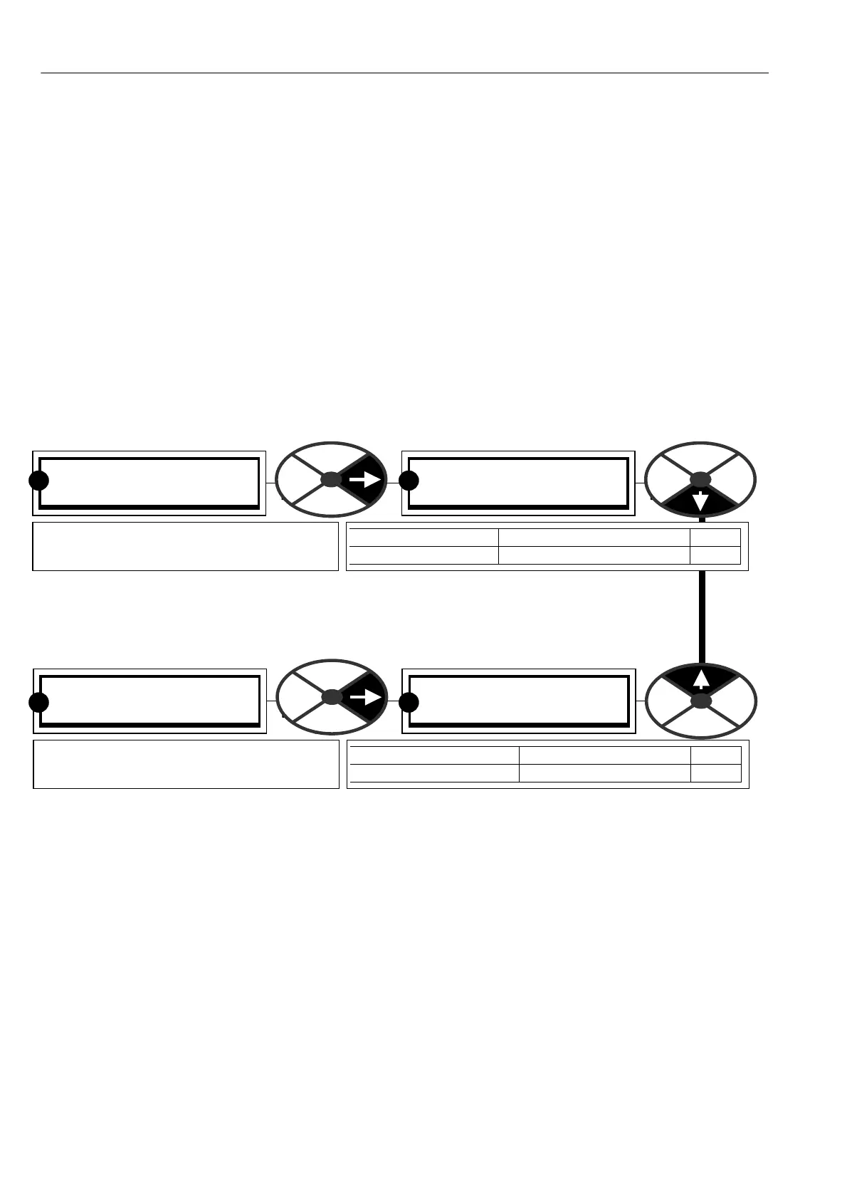
170)DC KILO W A TTS MON
170)DC KILO W A TTS MON
0.0
PARA METER RANGE PIN
DC KILO W A TTS M ON + /-3000.0 K W 170
Shows the output po wer at the drive
A + / A- terminals in Kilowatts.
R R
DIA GNOSTICS 2
169)EL1/2/3 RMS M ON
169)EL1/2/3 RMS M ON
0.0 V
PARA METER RANGE PIN
EL1/2/3 RMS M ON 0.0 to 1000.0 V 169
Shows the rms A C supply voltage applied
to the EL1, EL2, EL3 terminals. ( + /-5 %)
R R
7.6.1 BLO CK OP M ONIT OR / General description
The majority of the functional blocks within the system are also provided with an output monitor in the block
menu listing. It is normally the first window . The outputs are contained in each block listing because it is
convenient to have the output monitor adjacent to the relevant adjustment parameters w hen programming.
In addition all the block outputs are grouped together in this menu for rapid sequential access if required. The
block output monitor order is the same as the order of the blocks in the BLO CK OP C ONFIG configuration
menu. See 13.11 C ONFIGURATION / BLO CK OP C ONFIG.
7.7 DIAGNOSTICS / EL1/2/3 RMS MON PIN 169
Note. With no applied voltage there may be a small offset. This does not affect the actual
reading.
7.8 DIAGNOSTICS / DC KILOWATTS MON PIN 170
Note. A negative output po wer shows that the PL/X is regenerating into the AC supply.
The power available at the motor shaft will depend on the motor efficiency. (Typically 90 to 95 %).
To convert Kilo watts to Horsepower multiply by a scaling factor of 1.34.
Note for the PL/XD stack driver, which may be used in applications in excess of 3000Kw then this parameter
is clamped at 3000Kw. This equates approx. to 7500 A at 400V armature or 4000 A at 750V armature.
See separate PL/XD Stack Driver manual for further details of this unit.