114 CHA NGE PARA METERS
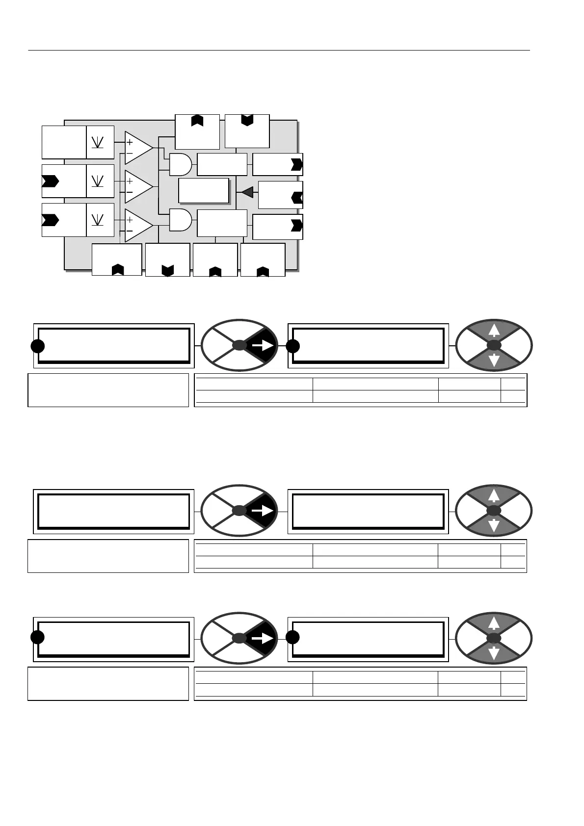
6.10.1 ZERO INTERLO CKS / Block diagram
6.10.2 ZERO INTERLOCKS / Standstill enable PIN 115
If enabled, the standstill function will inhibit the stack firing when there is zero reference A ND zero speed.
This parameter must be DISABLED for 6.10.9 ZERO INTERLO C KS / SPINDLE ORIENT A TE operation.
6.10.3 ZERO INTERLO CKS / Zero reference start enable PIN 116
6.10.4 ZERO INTERLOC KS / Zero interlocks speed level PIN 117
The signals being detected are total speed reference and speed feedback. The input depends on the function
(total speed reference for standstill, and total speed inputs prior to the normal ramp for zero reference start).
This speed level also sets the threshold for 120)A T ZERO SPD FLA G.
ZERO INTERLO CKS 3
115)STANDSTILL ENBL
115)STANDSTILL ENBL
DISABLED
PARA METER RANGE DEF AULT PIN
ST ANDSTILL ENBL EN ABLED OR DIS ABLED DISABLED 115
Allo ws the standstill function
to be enabled.
R R
ZERO INTERLO CKS 3
116)ZERO REF ST ART
116)ZERO REF ST ART
DISABLED
PARA METER RANGE DEF AULT PIN
ZERO REF ST ART ENABLED OR DIS ABLED DIS ABLED 116
Allo ws the zero reference start
function to be enabled.
ZERO INTERLO CKS 3
117)ZERO IN TLK SPD %
117)ZERO IN TLK SPD %
1.00 %
PARA METER RANGE DEF AULT PIN
ZERO INTLK SPD % 0.00 to 100.00% 1.00 % 117
Sets speed level for the zero
ref start and standstill blocks.
R R
Total speed
Ref + ref prior
to the Run
Mode Ramp
ZERO
Interlock
PIN 11 7
Zero interlocks
Speed level
PIN 123
Total
Speed
Reference
PIN 120
Zero speed
flag
Rect
PIN 131
Speed
Feedback
PIN 119
Zero ref flag
Rect
Rect
Rect
PIN 116
Zero ref
Start enable
Zero ref start
control logic
To current
control logic
PIN 118
ZI current
level
PIN 12 1 At
S’still flag
To firin
ccts
PIN 115
Standstill
enable
PIN 122
Zero speed
lock
Standstill and
position lock
control logic