Menu tree stucture 47
5.1.1 Incrementing and decrementing parameter values.
This is achieved using the up/down keys. All the parameters that may need changing have been placed at the
end of a branch where the up/do wn keys change the parameter value instead of travelling. After the value
has been changed it will be retained simply by backing out of that menu location using the left key.
Note. Values that are very large can be changed quickly by holding the key down which will introduce an
accelerated change rate. Releasing the key returns it to a one-shot mode. When running, most windows will
allow a parameter change to occur as the value is changing, as if a potentiometer was being adjusted. Some
windo ws will request STOP DRIVE TO ADJUST if an immediate change is preferable at standstill.
5.1.2 PARAMETER S A VE
Storing the altered values in the drive so that they are retained when the control supply is removed.
This is achieved by travelling to the PARA METER SA VE location in the main menu. Press the right key to
enter the PARA METER S A VE windo w. Once there, using the UP key saves all the presently prevailing
parameter values. The bottom line of the display will read SA VING and then FINISHED.
If you wish to abandon changes made since the last save, simply remove the control supply WITHOUT
having performed parameter save. See 13.13.2 DRIVE PERSO NALITY / Recipe page PIN 677.
Note. If the control supply dips below 80V A C without going totally off then an automatic save of the last
DRIVE TRIP MESSA GE occurs. Any other parameters with the power loss memory facility are also saved.
(E.g. M OT ORISED PO T output). There is a hidden PIN 681 Power.S A VED ONCE MON. which is set high to
indicate this has occurred. This flag is reset to zero if the internal supplies go totally off and back on again.
See also 8.1.11.1 1 DRIV E TRIP MESSAGE / Supply phase loss.
5.1.3 Restoring the drive parameters to the default condition
Sometimes it is useful to return a unit to its default setup condition. E.g. a trial configuration may prove to be
un workable and it is easier to start again. If all 4 keys are held down during the application of the control
supply, then the drive will automatically display the default parameters and connections. (EXCEPT those in
the CALIBRATION menu, and 100)FIELD VOLTS OP % for MOTOR 1 and MOTOR 2, and 680)Iarm BURDEN
OHMS. The se parameters remain as previously calibrated to prevent accidental de-calibration when restoring
defaults). The defaults will only be permanently retained how ever if they are saved using the PARAMETER
SA VE menu. To revert to the last saved set, turn the control supply off, without doing a PARA METER SA VE.
Also the PASSWORD is reset to 0000. See 11.2 DISPLA Y FUNC TIONS / PASSW ORD C ONTROL. See also
13.13.2 DRIVE PERSO N ALITY / Recipe page PIN 677, for details of 2 and 3 key reset operation and po wer
up messages.
5.1.4 Branch hopping between monitor windo ws
One large class of menu is the DIAGNOSTICS. This provides a very comprehensive monitoring facility of
analogue linear input signals, control logic levels, alarms and internal parameters. Each parameter to be
monitored is sighted at the end of a branch. Here the up/do wn keys allo w hopping to the adjacent branch.
This removes the need to travel back to the previous level and allo ws rapid observation of multiple
parameters. Branch hopping also occurs any w here there are t wo or more adjacent monitoring windows.
5.1.5 Power up windo ws
A fe w seconds after the control supply is applied, the ENTRY MENU window is show n, after a further brief
pause with no keystokes, two default % DIAGNOSTIC summary windows are activated. See 5.1.6.
The control card interrogates the po w er chassis during power up to find out the model type. This allo ws the
transference of the control card to a different pow er chassis. See 13.13.4 DRIVE PERSONALITY / Armature
current burden resistance PIN 680. See also 13.13.2 DRIVE PERSON ALITY / Recipe page PIN 677.
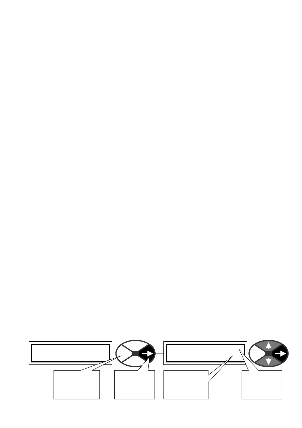
By tapping the right key you will enter the first of the menu levels of the menu tree.
PRESS RIGHT KEY FOR
ENTRY MENU LEVEL 1
ENTRY MENU LEVEL 1
CH A NGE PARA METERS 2
This number
sho ws which
menu level
you are in
This number
sho ws the next
menu level you
will proceed to
Tap right key
to proceed to
next menu
level
Tap the left key
to return to the
previous menu
level