CHA NGE PARA METERS 93
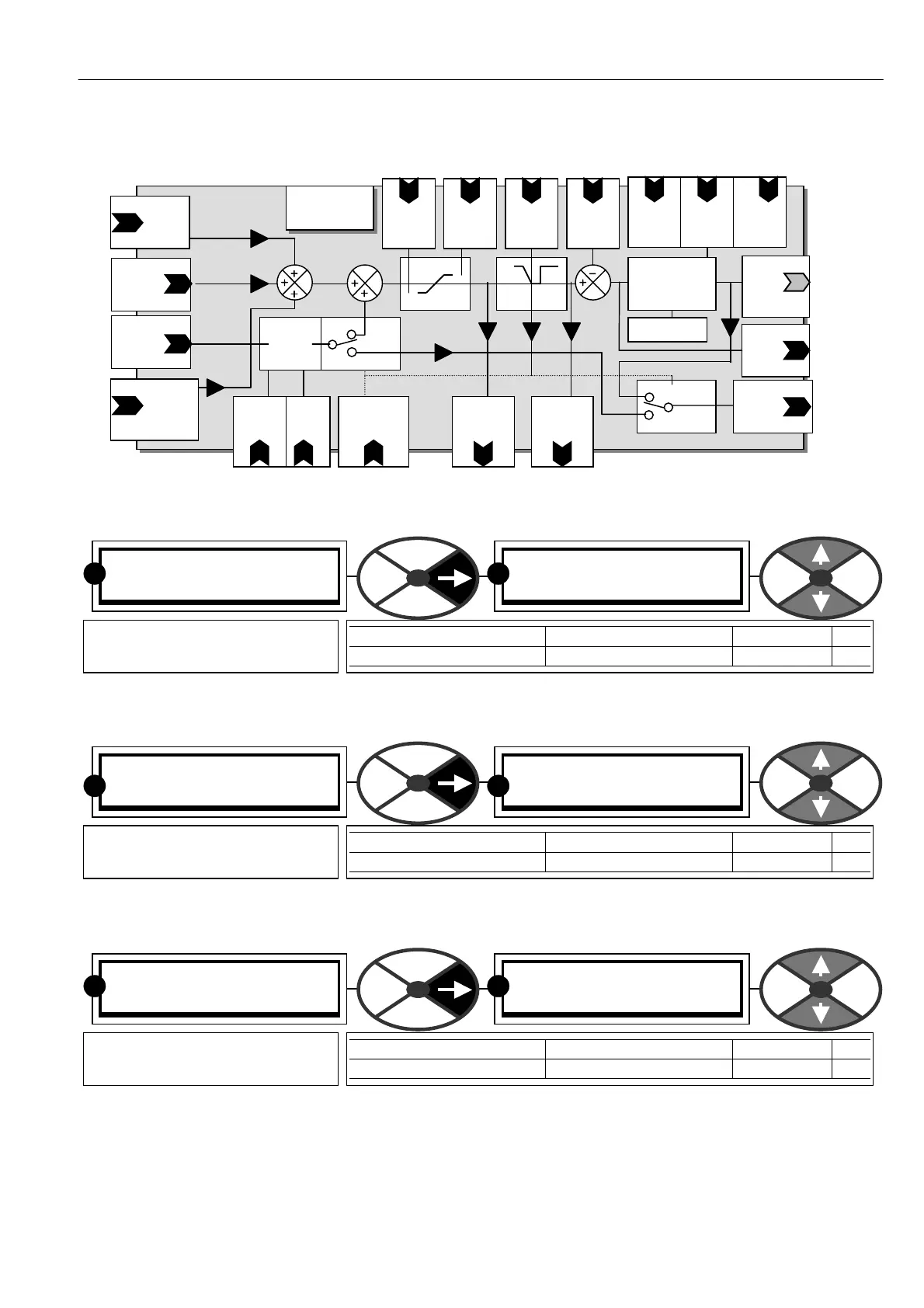
6.7.1 SPEED CONTROL / Block diagram
6.7.2 SPEED CONTROL / Max positive speed reference PIN 69
6.7.3 SPEED CONTROL / Max negative speed reference PIN 70
6.7.4 SPEED CONTROL / Speed proportional gain PIN 71
Increase to improve response time, excessive values may cause instability.
SPEED CONTROL 3
69)M A X POS SPEED REF
69)M A X POS SPEED REF
+ 105.00 %
PARA METER RANGE DEFAULT PIN
M A X POS SPEED REF 0.00 to + 105.00 % 105.00 % 69
Sets positive (forward) limit
level of total speed reference.
RR
SPEED CONTROL 3
70)M A X NEG SPEED REF
70)M A X NEG SPEED REF
-105.00%
PARA METER RANGE DEFAULT PIN
M A X NEG SPEED REF 0.00 to -105.0 0% -105.00% 70
Sets negative (reverse) limit
level of total speed reference.
R R
SPEED CONTROL 3
71)SPEED PROP G AIN
71)SPEED PROP G AIN
15.00
PARA METER RANGE DEFAULT PIN
SPEED PROP G AIN 0.00 to 200.00 15.00 71
Sets the proportional gain of
the speed loop error amplifier.
RR
PIN 62
Int Ref 1
Default
Motorised pot
SPEED
CONTROL
PIN 63
Spd Ref 2
Default
Terminal 2
Current
referenc e
Stop
ramp
time
Pin 56
Max
- ref
PIN
7
M ax
+ re f
PIN
PIN 69
PIN 70
run
Stop
ramp
Spd Int
Rese t
PIN
Sp Prop
G ain
PIN
Spd Int
time
PIN
PI adaption
Speed
bypass
enable
PIN 97
Speed Error
amplifier
P + I
Speed
Feed
Back
Input
PIN 64
Speed
Ref 3 Mon
Def Terminal 3
+ /- 1
and
X
Ref 3
ratio
PIN 67
Current
referenc e
Cur reference
Internal
connection
to current loop
Speed loop
PI
output
No display
PIN 713
Ref 3
sign
PIN 66
PIN 65 Ref 4
Default
From
Run mode ramp
block output
Speed
demand
monitor
PIN 124
Total
Speed Ref
monitor
PIN 123
Speed error
monitor
PIN 125