90 CHA NGE PARA METERS
SPEED REF SUMMER 3
67)SPD/CUR RF3 RA TIO
SPEED REF SUMMER 3
62)INT SPEED REF 1
SPEED REF SUMMER 3
66)SPD/CUR REF3 SIGN
SPEED REF SUMMER 3
63)SPEED REF 2
SPEED REF SUMMER 3
64)SPEED REF 3 MON
SPEED REF SUMMER 3
65)RA MPED SPD REF 4
R
R
R
R
R
R
MO T ORISED PO T RA MPS 3
52)UP TIME 4
CH A NGE PARA METERS 2
SPEED REF SUMMER 3
R
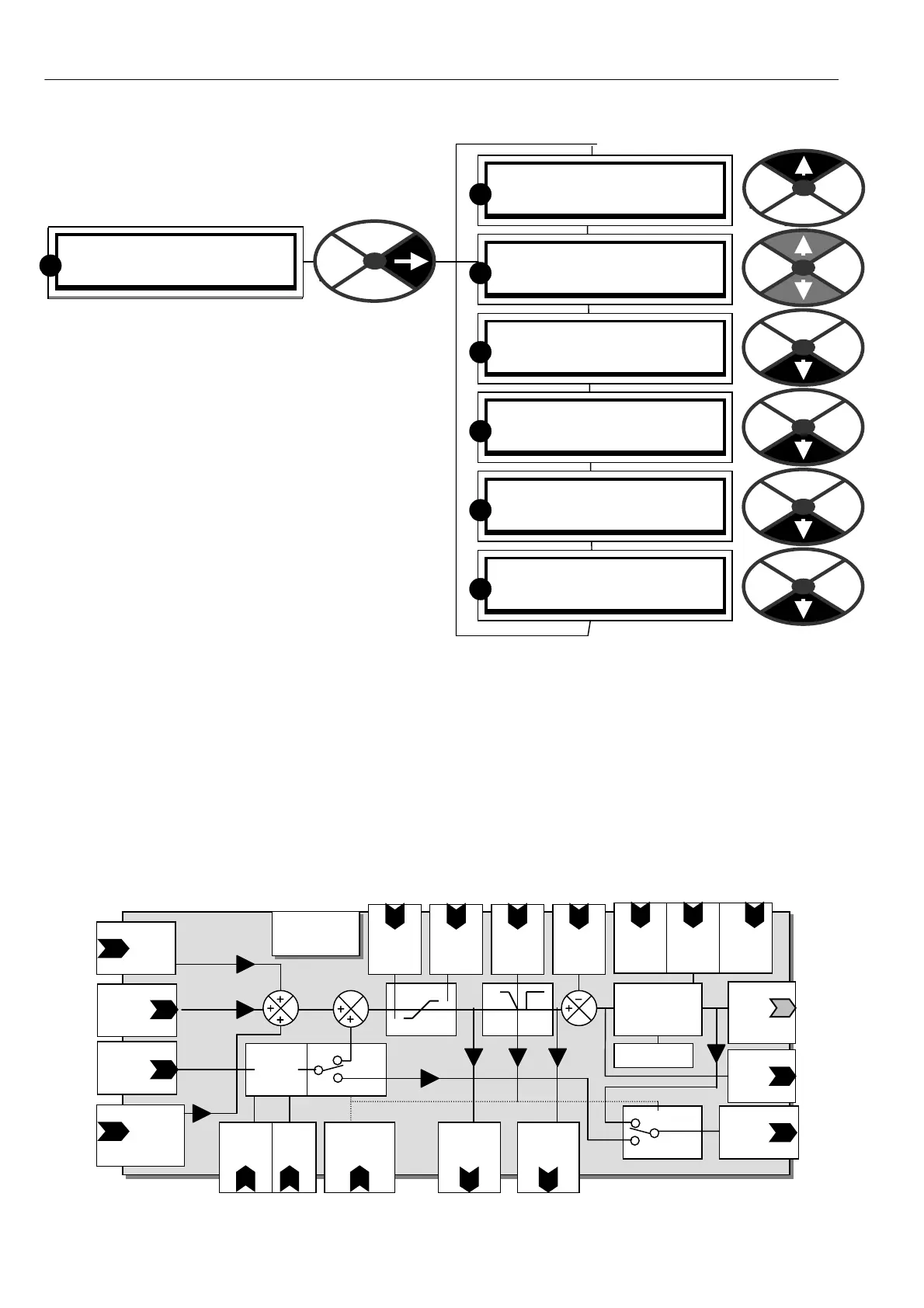
6.6 CHANGE PARAMETERS / SPEED REF
SUMMER
PIN numbers range 62 to 67
The block diagram below sho ws
the signal paths for the speed loop error amplifier.
There are 4 speed reference inputs.
Connections. (62, 63, 65 may be re-programmed)
Motorised potentiometer to 62)INT SPEED REF 1.
UIP2/T 2 To 63)SPEED REF 2
UIP4/T 4 - Run mode ramp to 65)RAMPED SPD REF 4
UIP3/T 3 Internally connected to 64)SPEED REF3 MO N
64)SPEED REF 3 MON is a monitor of UIP3 only w hen
it is being used as a speed ref with speed bypass
disabled. . It may be inverted and/or scaled if desired.
It is sampled rapidly to give maximum response.
See 6.8.14 CURRENT C O NTROL / Speed bypass
current reference enable PIN 97 .
Note. The STOP command overides and disables the
speed bypass mode. This ensures a controlled stop to
zero speed when using the speed bypass mode.
The inputs are summed and then subjected to programmable maximum + ve and –ve clamps. The output
after the clamps is the final speed reference w hich is available to be monitored. This is selected during
normal running. During a stop sequence this is reset to zero at the programmed STOP rate. See 6.2 CH A NGE
PARA METERS / RUN MODE RA MPS for information about the run mode ramp resetting functions. The stop
ramp is released immediately when running is resumed. The output after this selection is the speed demand
and is summed with negative speed feedback to produce a speed error. This is then processed in the speed
loop P + I error amplifier. The output of this block is the current reference that is sent to the current control
blocks during normal running. See 6.7 CHAN GE PARAMETERS / SPEED CONTROL.
6.6.1 SPEED REF SUMMER / Block diagram
PIN 62
Int Ref 1
Default
Motorised pot
SPEED
CONTROL
PIN 63
Spd Ref 2
Default
Terminal 2
Current
referenc e
Stop
ramp
time
Pin 56
Max
- ref
PIN
M ax
+ re f
PIN
PIN 69
PIN 70
run
Stop
ramp
Spd Int
Rese t
PIN
7
Sp Prop
G ain
PIN
71
Spd Int
time
PIN
72
PI adaption
Speed
bypass
enable
PIN 97
Speed Error
amplifier
P + I
Speed
Feed
Back
Input
PIN 64
Speed
Ref 3 Mon
Def Terminal 3
+ /- 1
and
X
Ref 3
ratio
PIN 67
Current
referenc e
Cur reference
Internal
connection
to current loop
Speed loop
PI
output
No display
PIN 713
Ref 3
sign
PIN 66
PIN 65 Ref 4
Default
From
Run mode ramp
block output
Speed
demand
monitor
PIN 124
Total
Speed Ref
monitor
PIN 123
Speed error
monitor
PIN 125