96 CHA NGE PARA METERS
6.7.7.6 SPEED PI A D APTIO N / Speed loop adaption enable PIN 79
The X-axis internal connection is the speed error signal.
The default values in this SPEED PI A D APTIO N sub-menu are chosen as a starting point.
The most frequently encountered requirement is for the gain term of the speed loop error amplifier to be high
for large speed errors, and low for small errors.
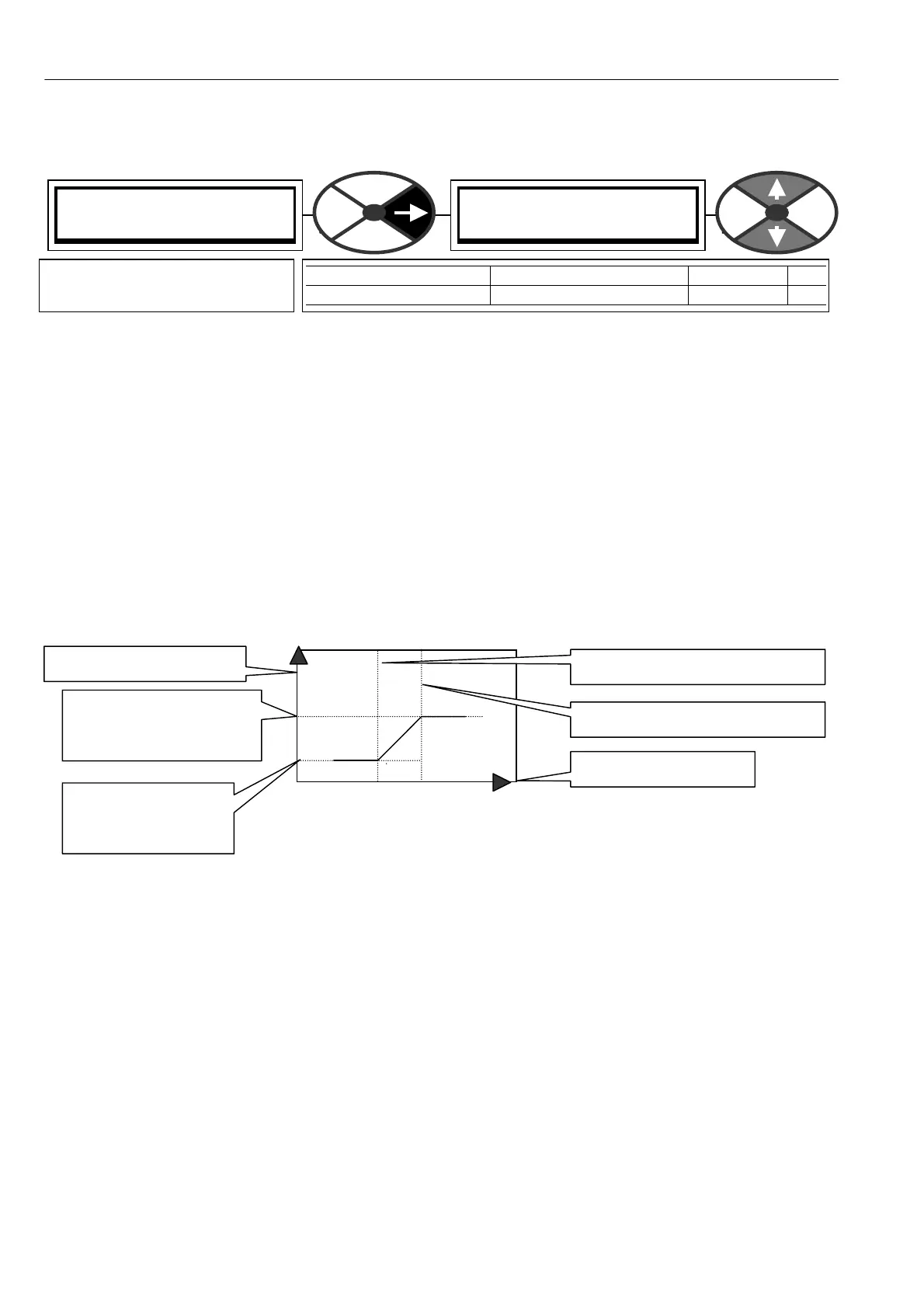
When the function is enabled the default values of prop gain are 5 for errors below 1.00 %, and 15 for errors
above 2.00% with a linear change from 5 to 15 bet ween 1.00 % and 2.00%.
A decreasing gain with error is also possible by choosing appropriate term values in this and the upper SPEED
CONTROL menus.
Graph of adaption profile for default values.
Note. The default settings are de signed to give lower gain with low error. This provides smooth steady state
performance. Applications that require preci se control at very low speeds may function be tter with the
adaption disabled.
See also 6.10.8.1 Low speed performance
6.7.7.7 SPEED PI A D APTIO N / Using small speed inputs
Some applications utilise very small speed inputs e. g. positioning. In this case the default settings for the
SPEED PI AD APTION may be unsuitable. This is because they are designed to give lo w gain for low errors
which provides smooth running at speed.
For small inputs it may be necessary to either DIS ABLE the function, or modify the parameters to
provide higher gain for small errors. See 6.10.8.1 Lo w speed performance.
SPEED PI AD APTIO N 4
79)SPD ADAPT ENABLE
79)SPD ADAPT ENABLE
ENABLED
PARA METER RANGE DEF AULT PIN
SPD A D APT EN ABLE EN ABLED or DIS ABLED EN ABLED 79
Enables the mode that varies
the terms between break points
Set in THIS MENU.
LO prop gain of 5
LO Int TC of 1.00 0
LOW BREAK POINT of 1.00%
HIGH BREA K POINT of 2.00%
X axis is speed error
Y axis is P and I terms
Set in UPPER MENU.
Speed Prop gain of 15
Speed Int TC of 1.000