CHA NGE PARA METERS 117
To summarise.
The orientation function is activated by dropping belo w the zero speed threshold. 24 1)M ARKER OFFSET is
actioned only once at the commencement of orientation, and 242)POSITION REF is then follo w ed with
respect to the 241)MARKER OFFSET position. The orientation function is de-activated by increasing the
speed demand above the zero speed threshold.
242)POSITIO N REF may be changed as many times as required and the shaft position will track it relative to
the 241)M ARKER O FFSET position. Each time 242)POSITION REF is changed to a ne w value, the 244)IN
POSTION FLAG may be used to determine when the ne w position has been achieved.
The gain and hence response of the position control loop is set by 122)ZERO SPEED LOCK. A value of zero
will turn off the position loop. The block also provides 243)M ARKER FREQ MO N giving marker frequency.
For systems that require position locking at zero speed but the absolute position is not important, then
122)ZERO SPEED LO CK only may be used. In this case no marker is required, and the 240)M ARKER EN ABLE
input should be set to disabled.
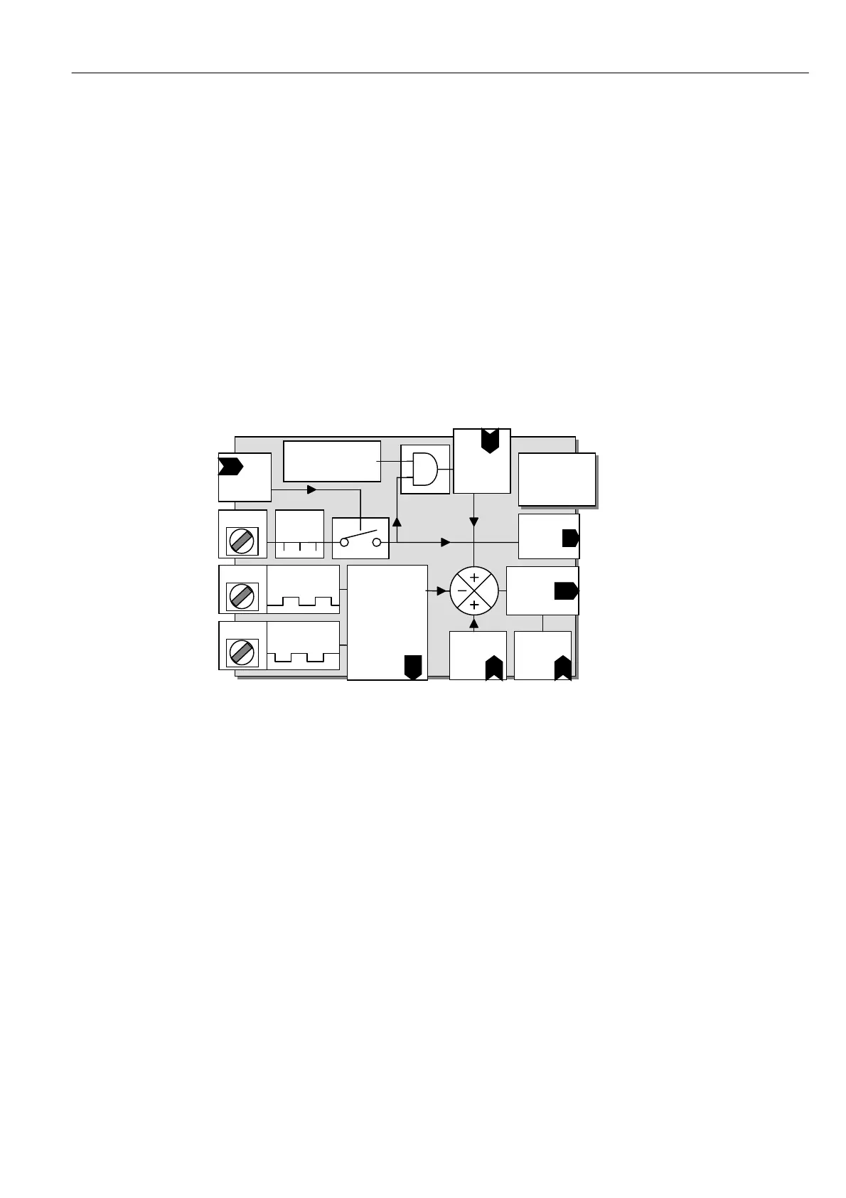
6.10.9.1 SPINDLE ORIENT A TE / Block diagram
6.10.9.1.1 Spindle orientate operation
For all speeds above 117)ZERO INTLK SPD %, the spindle orientate control action is disabled. However the
marker frequency monitor will function within its defined limits providing 2 40)M ARKER EN ABLE is enabled.
Note. The marker that is used for orientation is the la st one to be input prior to the spe ed falling below
117)ZERO INTLK SPD % threshold. ( This is normally within 1 revolution of the shaft prior to the threshold).
When the speed falls below 117)ZERO INTLK SPD %, then the spindle orientate function will operate
providing 122)ZERO SPEED LO CK is set to a non-zero value and 240)M ARKER ENABLE is enabled. Once the
block has commenced functioning, it will continue as long as the speed demand is below 117)ZERO INTLK
SPD %. The actual speed may exceed 117)ZERO IN TLK SPD % without turning the block off.
The sequence of operation is as follows.
1) Speed demand and feedback fall and remain below 117)ZERO INTLK SPD % for 400mS. (Includes
Stopping sequences using terminals T33 or T32). (*PL models can only orientate when stopping).
2) Spindle orientation block is activated.
3) The shaft position at the last marker to be input prior to the speed falling below 117)ZERO IN TLK SPD %
is calculated by the PL/X.
4) The shaft seeks the 241)M ARKER O FFSET position.
5) As the shaft approaches the marker offset positi on the block checks for the 242)POSITION REF target.
SPINDLE
ORIENT ATE
PIN 242
Position
Ref
BIDIREC TION AL
PULSE C OUNTER
Shaft position
feedback count
PIN 24 4
IN Position
FLA G
PIN
24 1
M ARKER
OFFSET
(One shot)
Output
To
position
Control loop
T 1 5
T 15
M ARK
PULSE
Below Zero Interlock
Speed % (PIN 11 7)
Threshold
Terminal 1 6
FB PULSE B
T 1 6
Terminal 1 7
FB PULSE A
T 1 7
PIN 243
Marker
Freq OP
PIN
240
Marker
Enable
PIN 122
ZERO
SPEED
LO C K